Diagnosing video signal loss on Wii and GBS-Control
on
Last year I bought a GBS-Control to upscale and transcode game consoles for a VGA CRT monitor, and have been using and developing for it since. A few months ago, while playing my Wii in 480p with the GBS-C in passthrough mode (zero-latency non-scaling transcoder), I started getting random black screens every few hours. While I initially suspected a simple software problem, locating the cause of this bug spiraled into a multi-month adventure involving overheating chips, transmission-line time-delay measurements, and chasing RF interference.
(This article assumes an understanding of analog video sync timings, and how sync is is encoded on component luma or VGA hsync and vsync lines. For background, check out my previous article on CRT timings.)
GBS-C debugging
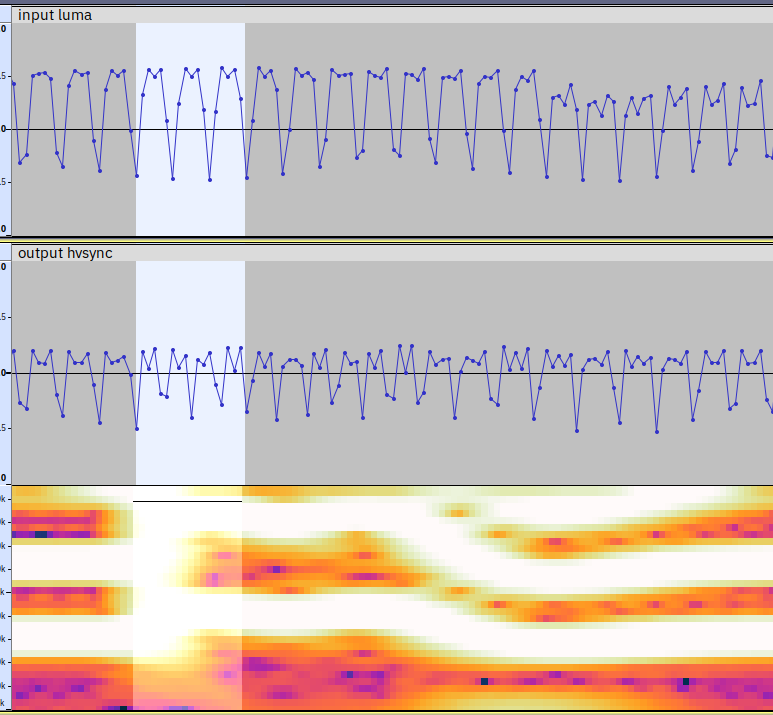
I initially suspected the GBS-C was outputting too short of a horizontal sync pulse over VGA, and my monitor would randomly fail to sync to it. But when I edited the firmware to output even shorter hsync pulses, my monitor still seemed to sync fine. After I observed the GBS-C's output VGA sync signal using my computer's 192khz motherboard audio line-in jack, I found that the actual problem was that the horizontal sync signal would randomly spike to a high frequency, before dropping down to a lower frequency and locking onto the input's phase again. I could not notice any input signal errors, using the audio capture hardware I had at the time.
At first, I confused the bug with a known bug where the GBS-Control PCB comes with a too-large AC-coupling capacitor on the scaler chip (TV5725)'s sync-on-green pins (here handling sync-on-luma), causing the screen to lose sync on white flashes. I replaced the capacitor, but the random signal loss (not connected to white flashes) continued. Then I started looking into GBS-C chip sync processor registers. While debugging the control flow, I found multiple issues with how the firmware was configuring scaler registers in passthrough mode, including a horrifying failure mode where it was handling Wi-Fi requests while talking to the hardware over I2C. I fixed the issues pertaining to hardware configuration, which didn't fix the problem.
At this point I suspected the GBS-C was incorrectly configuring the PLL used to track input sync pulses with the wrong divisor, voltage, and gain settings. I noticed that touching the PCB near the scaler chip's PLLAD pins would cause the image to shift horizontally or lose sync, so I assumed the problem was located in this area. After reading the PDF and crunching the numbers on its formulas, I reprogrammed the chip with the correct PLL register values, but the sync losses continued.
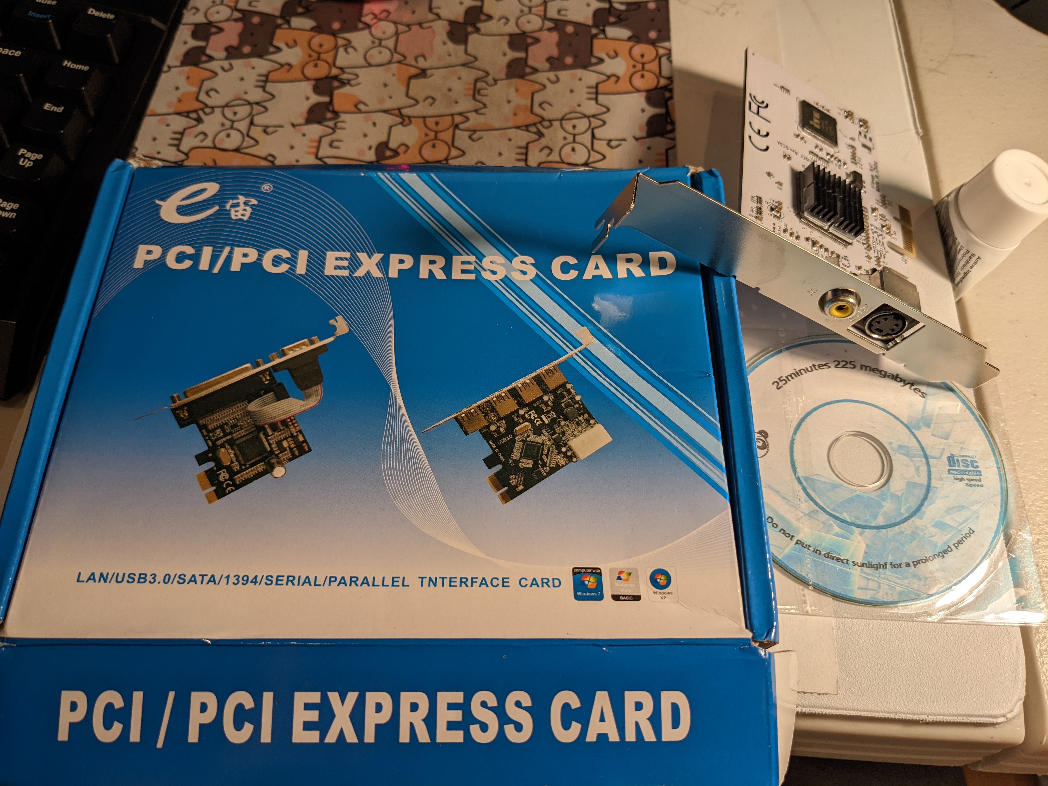
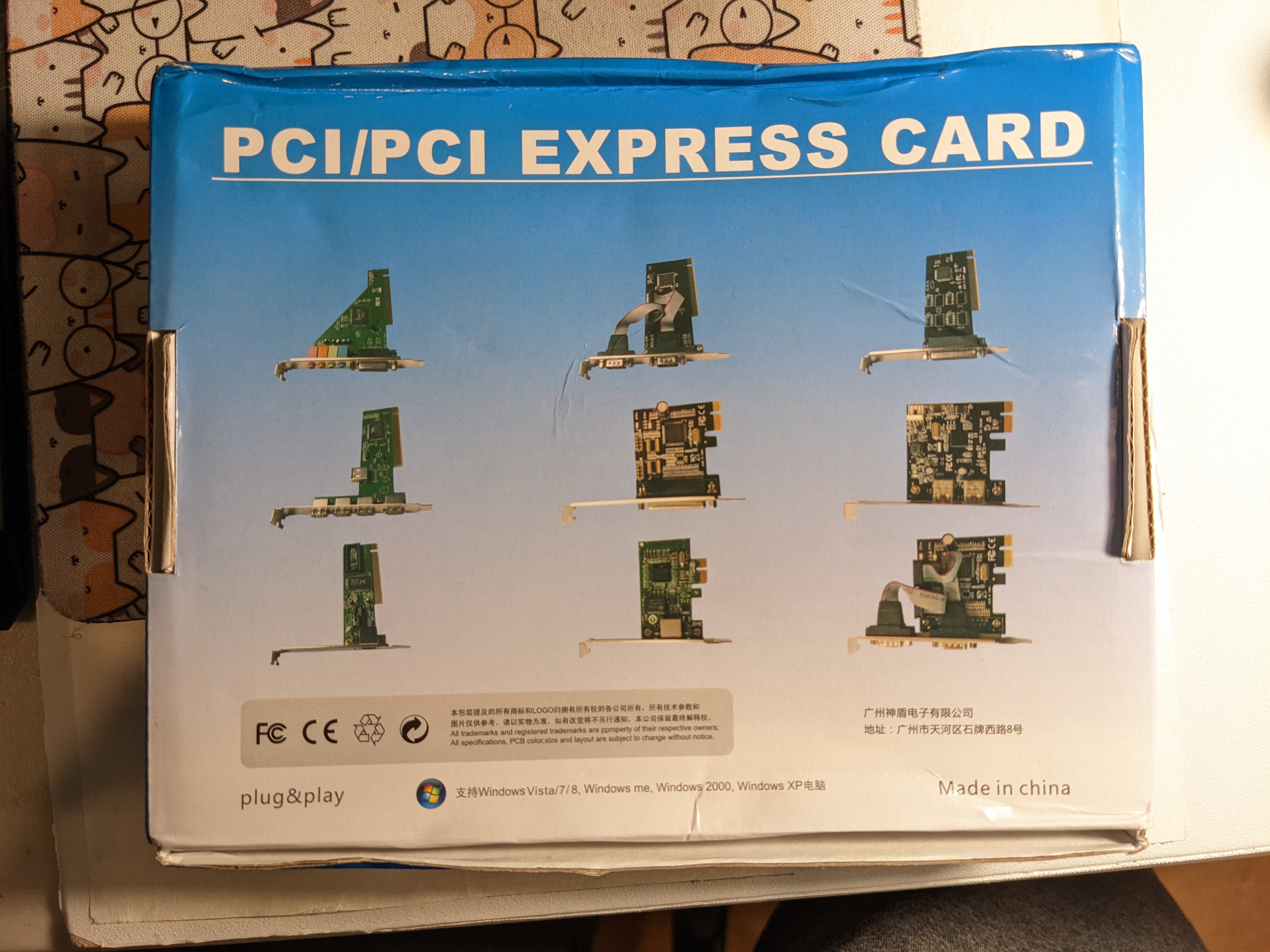
I was beginning to suspect an analog hardware malfunction, and wanted a way to view the input and output signals in more detail (resolving frequencies above 96 KHz), but didn't want to invest hundreds of dollars on an oscilloscope. So I bought a $25 CXADC PCIe capture card (with the most hilariously generic box art) which could sample analog data at 8 bits and around 28 MHz, and transfer it to a computer. Then I wrote a computer program to continually log data to a circular buffer in RAM, then save it to disk as a WAV file when I saw sync loss and pressed Enter.
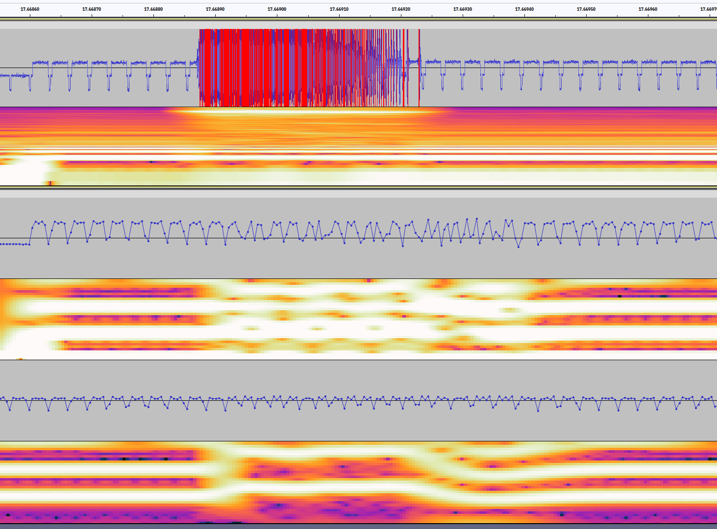
At this point I found ~8 MHz interference bursts on the GBS-C's input pins, and realized the GBS-C was outputting incorrect hsync frequencies after it saw noise on the input. I assumed this meant that the GBS was backfeeding noise onto the input, since I was getting similar input voltage fluctuations and noise when I power-cycled my GBS-C, and I'd never had similar issues with my Wii plugged into other TVs.
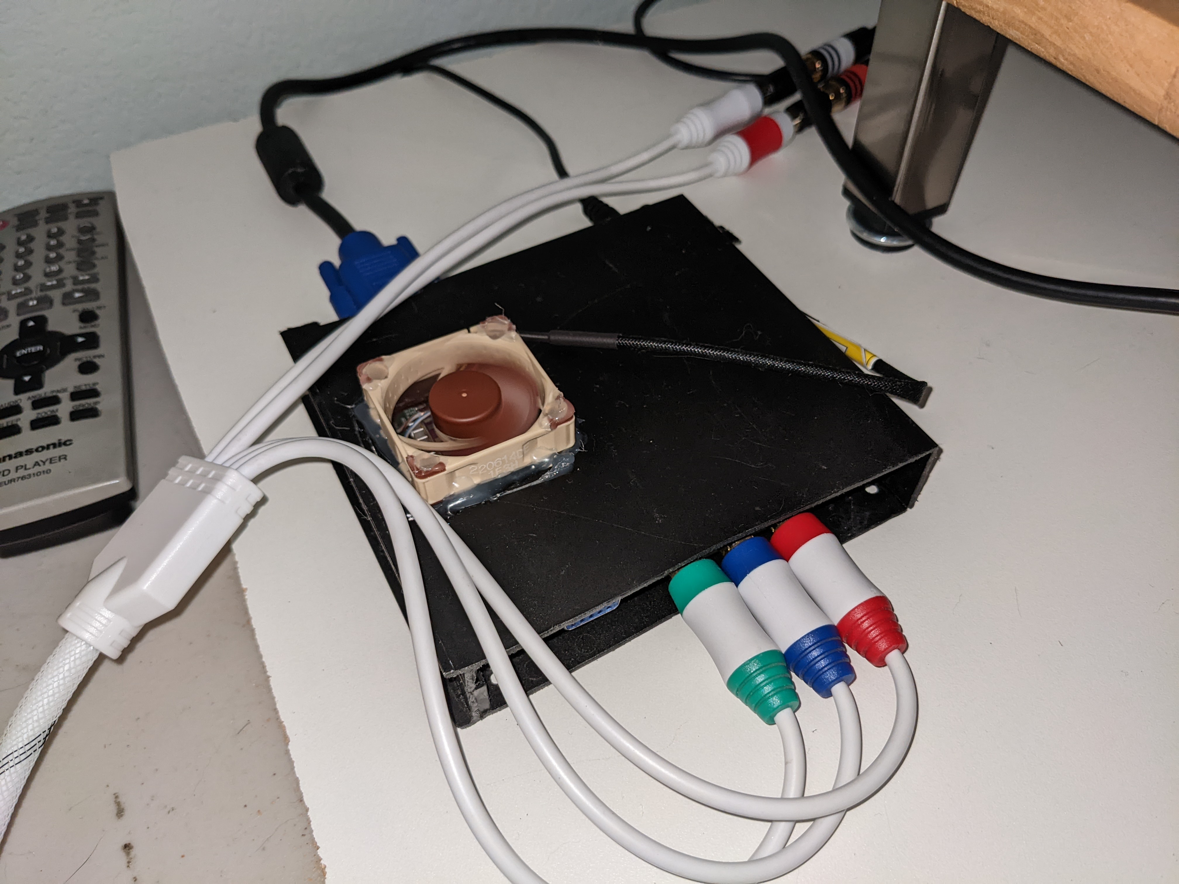
I suspected the GBS-C's scaler chip was malfunctioning from overheating. A measurement with a multimeter thermocouple revealed that the chip was reaching close to 60 degrees Celsius on a cold day (and more on a hot day), when my homemade GBS-Control case was closed up (also the thermocouple left me with painful fiberglass splinters in my finger). This was uncomfortably close to the chip's maximum allowed short-term temperature of 70 degrees. I tried adding a cooling fan to fix this, but the problem continued, so I assumed the chip was heat-damaged and injecting noise into its input.
Buying an oscilloscope
To confirm the GBS-C was producing noise spikes, I would have to measure whether the noise spikes arrived first at the Wii or GBS-C. Since it's difficult to synchronize multiple CXADC cards, I gave in and dropped $350 on a Rigol DS1054Z oscilloscope, with a user interface as laggy as running YouTube on a Pentium M laptop from 2003. The scope randomly fails to recognize or save waveforms to USB flash drives, especially when you've caught that one trace of an event that happens every few hours, and its CSV export excludes all but 1 channel by default and takes multiple minutes to complete. In hindsight, getting a real oscilloscope (though perhaps not this one) was the right decision, since the CXADC's sampling rate would not have been enough to resolve the 12 ns time delay of a signal traveling across 96 inches of shielded RCA cable serving as a luma extension cord.
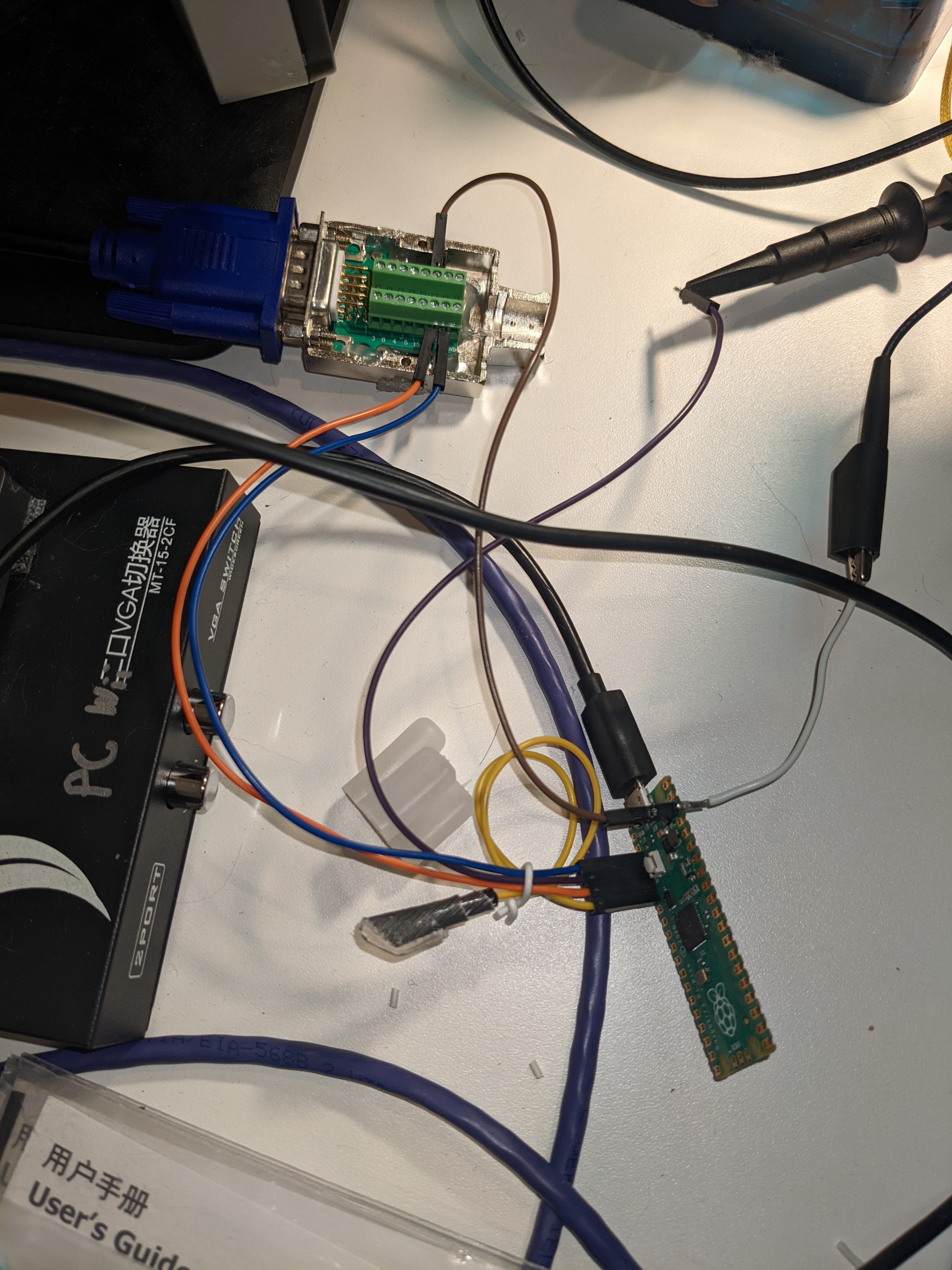
Because the Wii's video output is passed through a series capacitor (resulting in luma and sync having a variable DC offset during normal gameplay), the oscilloscope is unable to automatically identify when video noise produces voltages below sync pulses, unless you make the Wii output test signals with a fixed DC offset (eg. 240p Test Suite's solid color mode). So I wrote a program for a spare Pi Pico, which received 3.3V horizontal and vertical sync signals from the GBS-C's VGA output, timed the hsync signals to make sure they occurred at around 31.5 KHz, and verified that there were between 524 and 526 hsync pulses per vsync pulse.
While writing the program, I encountered several bugs, including a fencepost error when storing previous hsync timestamps, possibly having to debounce the GBS-C's hsync pulses, and a startup bug while counting lines before a vsync. I had to debug my code using solely GPIO output to expose information, since enabling serial debugging over USB slowed the Pico down so much it could not accurately measure the interval between hsync signals. (I assumed the slowdown occurred even when not printing, because the program was stalling on listening for serial input from the computer, though I may have been wrong.) Eventually I got the program working to a point it could reliably detect VGA sync interruptions and tell the scope the signal was lost, so the scope could save the input luma data before and after the sync loss.
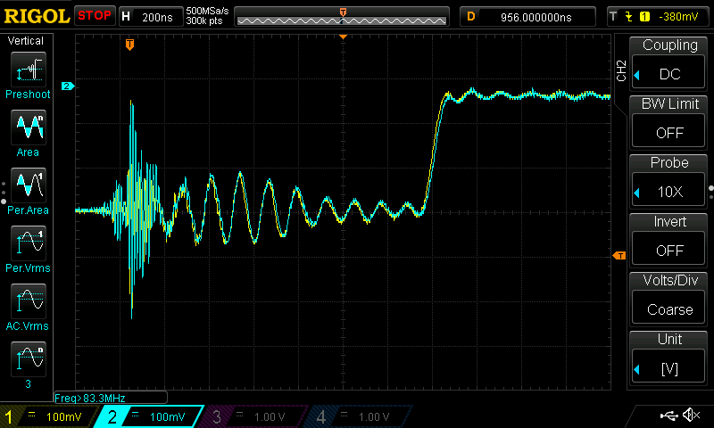
Using my scope to measure the signal's phase at both ends of my luma extension cord, I found that the 8 MHz oscillations actually originated at the Wii rather than the GBS-C. Additionally I found frequent bursts of high-frequency noise (IIRC around 100 MHz?) in patterns resembling the noise bursts, which appeared at the same time on both probes (or possibly even earlier on the GBS-C). After further testing, I found that the 100 MHz noise stopped appearing when I unplugged my ESP8266 from the GBS-C's power rails, or unplugged my extra-long USB cable from the ESP's USB data port.
- I performed some of my analysis by saving waveforms from the oscilloscope to a CSV file on a USB flash drive, then plugging them into a computer and importing into PulseView on Linux. This allowed me to use the larger screen and faster processor on my computer to inspect and zoom around in the sample data.
At this point I concluded the GBS-C was picking up 100 MHz interference which caused the ground rail's voltage to fluctuate, causing the Wii to amplify this noise, and that unplugging the USB cable and shortening the ESP8266's power cable had fixed the problem. I was surprised to find that the Wii's 8 MHz noise bursts continued, present on both the video signal and (at a higher voltage!) when measuring across different points on my extension cord's shielding.
- Note that the oscilloscope probes' ground leads are all connected, introducing new ground paths which changes how the circuit responds to high-frequency signals and interference. I do not have multi-hundred-dollar differential probes to avoid this issue.
- It's possible that passing the probe cables through a ferrite bead/clamp can eliminate high-frequency currents through the ground leads. I have not tested this, nor gotten a response from asking more knowledgeable electrical engineers.
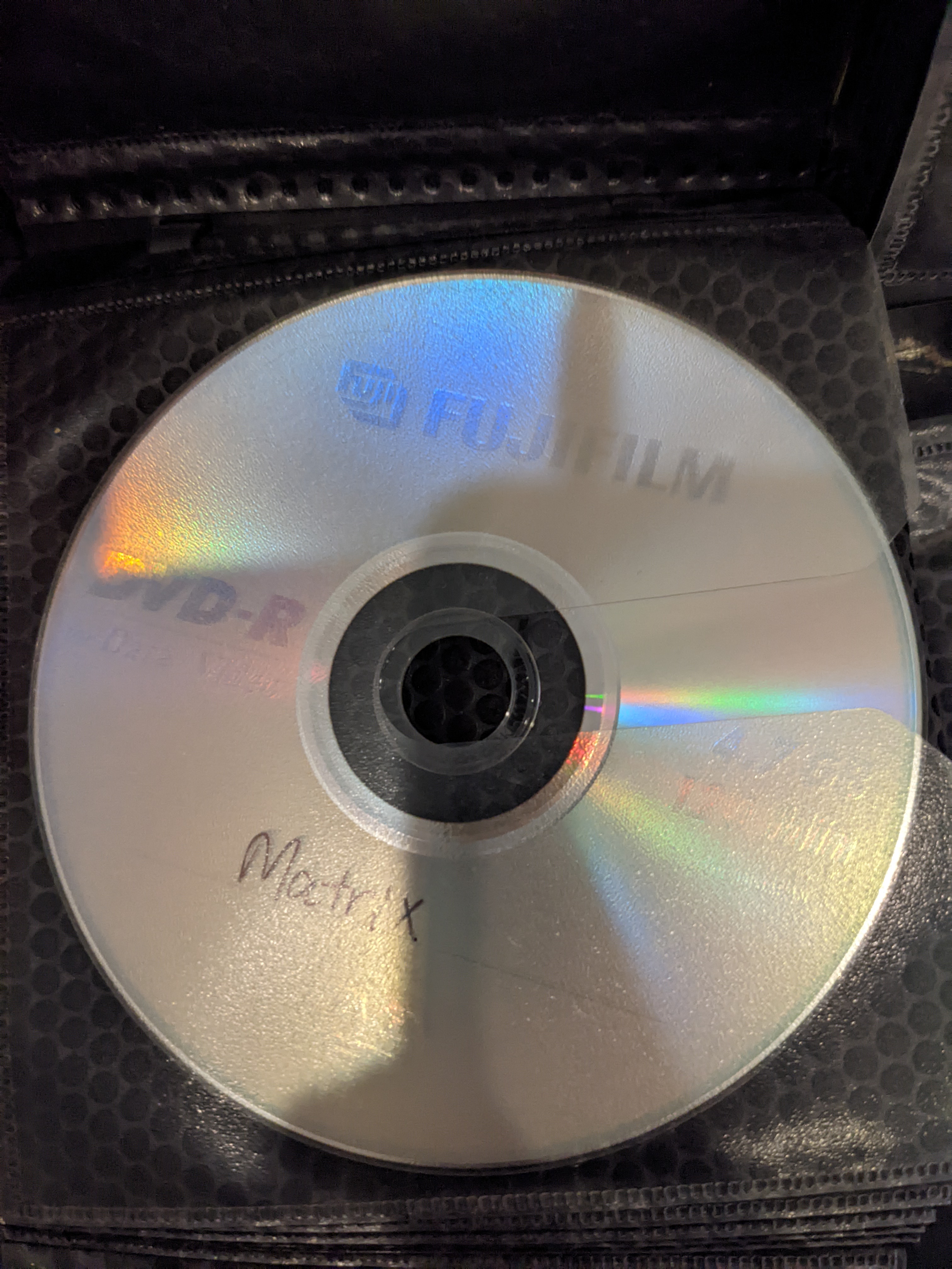
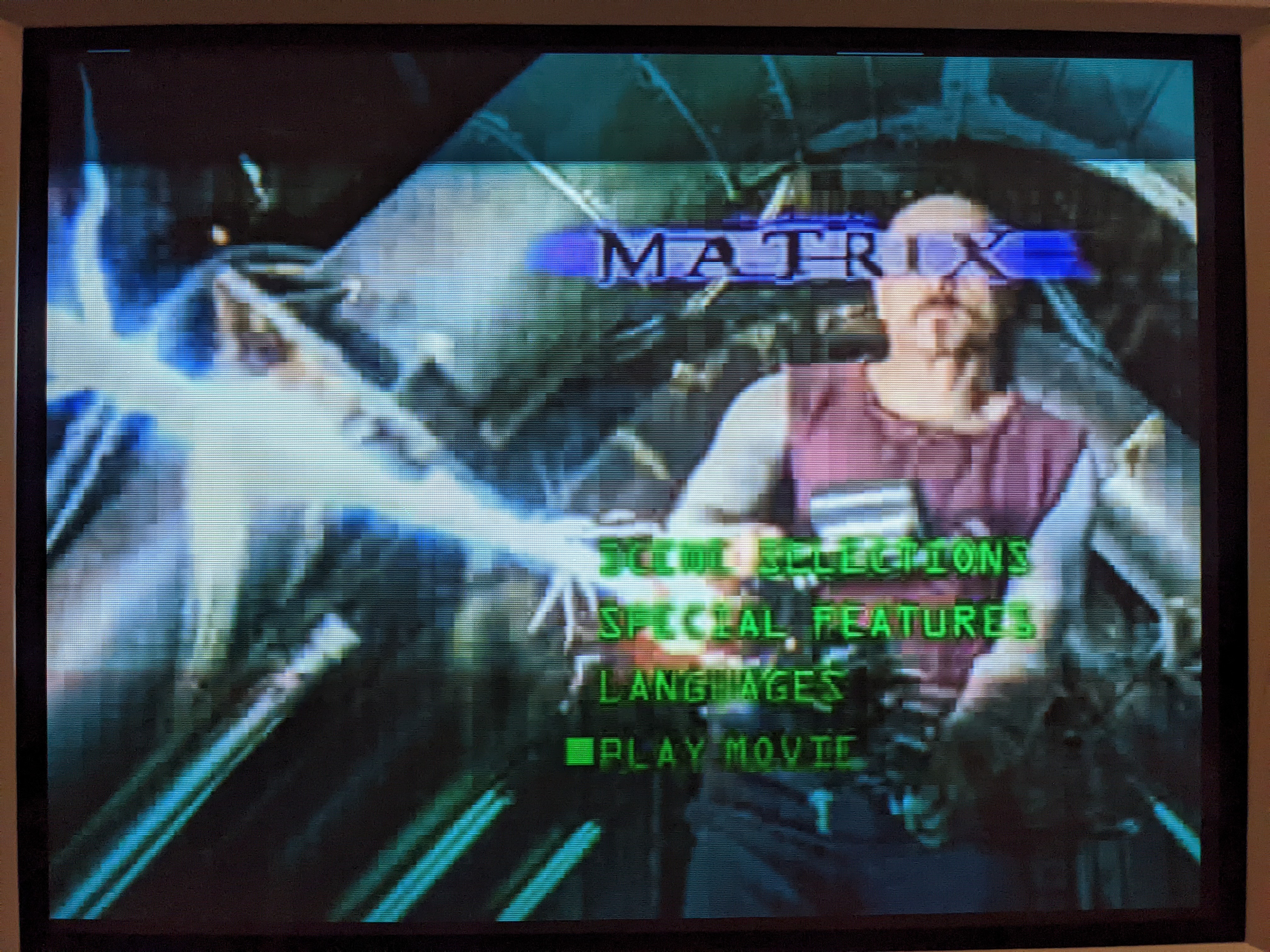
I also hooked up my GBS-C up to a DVD player. I had lost my DVD remotes but still needed to set the player into progressive scan mode. So after soldering together a 3.5mm-to-IR-led adapter using leftover LEDs and PCBs from my sensor bar project, I duct-taped the LEDs to my DVD player, installed irplus WAVE, plugged the LEDs into my phone's headphone jack, and found one of my two DVD players which were supported by the app. Afterwards I enabled progressive scan mode, set the DVD player to assume a 16:9 display (to avoid letterboxing and improve vertical detail), and fired up a pirated copy of The Matrix burned in the 2000s.
While playing around with this setup, I got several noise spikes (some of which even looked like they came from the GBS-C rather than the DVD player, though the shared probe ground makes it hard to know for sure), but no actual VGA sync loss. After letting the DVD player, GBS-C, and sync monitor Pico run overnight, the oscilloscope did not catch any sync loss incidents, suggesting the Wii was the only component video source to oscillate when connected to the GBS-C.
One interesting thing I noticed was that voltages were extremely sensitive to static shock. Plugging in a flash drive into my scope, brushing against the ground/voltage test points, rolling my chair across the wooden floor and plastic floor mat, or even touching my metal water bottle were all sufficient to create over a volt of high-frequency electromagnetic interference on my oscilloscope, leading to a spurious trigger event.
Returning to my Wii, my new theory was that I had coiled the extension cord into a loop antenna, which was picking up interference and driving the Wii into noise bursts. I removed the cord, thinking I had resolved the problem. Watching the oscilloscope revealed it hadn't.
At this point I started suspecting that the GBS-Control's power supply was inadequate, leading to noise at its luma input. My usual USB power supply (an old Motorola TurboPower 15W phone charger) delivered 4.86 volts (fluctuating slowly between 4.8 and 4.9x) at the GBS-C's current draw, and a powered USB hub only delivered 4.6 volts (a severe voltage sag), despite both being rated for the same 3 amps of output. My MacBook Air USB-C charger outputted 4.94 volts, which was much more stable than the other power supplies (although possibly more noisy). However, the sync loss continued.
Blaming the Wii
On a whim, I unplugged the GBS-Control's power supply altogether, and my oscilloscope still saw noise bursts coming from the Wii. At this point, I began thinking the Wii was outputting noise by itself, even without the GBS-Control in place (and somehow I had never seen the image loss on any other display). To confirm this, I bodged together a triple 75 ohm terminator on protoboard using RCA jacks I had purchased from Amazon (and cracked several SMD component legs off their bodies when trying to solder them without a PCB). I hooked my Wii up to this passive terminator, unplugged its audio jacks to avoid ground loops, and saw the same noise coming from the Wii. This confirmed that the GBS-C was not causing the Wii to drop signal.
I unplugged the USB hard drive and GameCube controller from my Wii, which continued to drop signal on my oscilloscope. I wanted to verify that my luma line's Y-splitter was not causing the interference, but removing it would leave me unable to check luma for sync loss. So I plugged the component cables into the GBS-C directly, and fed the GBS-C into my Pi Pico to check for sync loss. Again my oscilloscope showed the signal went high, indicating the Pico detected a loss of synchronization. At this point, I was confident the Wii itself was malfunctioning, regardless of what was plugged into the video and audio outputs.
Replacing the light switch
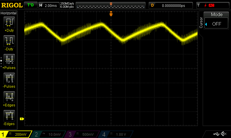
One potential source of signal interference I had not investigated up to that point, was the 3-way dimmer light switch on my wall. When I turned the slider up, there was a point it would suddenly dim the ceiling lights and take a good chunk out of the LED bulbs' light output waveform (relative to 120hz rectified AC power). Additionally the ceiling lights would randomly flicker when set near this brightness cutoff.
Having traced my display issue down to a malfunctioning Wii, I decided to replace the wall switch with a non-dimmer and see if anything would change. Hooking up a solar panel to the oscilloscope showed that my ceiling lights' output waveform was no longer broken. (Though sadly my LED ceiling lights still flicker at 120Hz by around 17% or so of their peak brightness, due to inadequate power filtering, and my room still suffers from a lot of RF interference, for god knows what reason.)
After removing the dimmer switch from the wall, I was surprised to find that in two days of on-and-off testing using my oscilloscope and Pico (and sometimes CRT) with the Wii displaying Homebrew Channel and Super Mario Sunburn, I haven't detected a single Wii sync loss event. This piqued my curiosity, and I decided to look inside to see if was wrong with the switch. And I was not prepared for what I found.
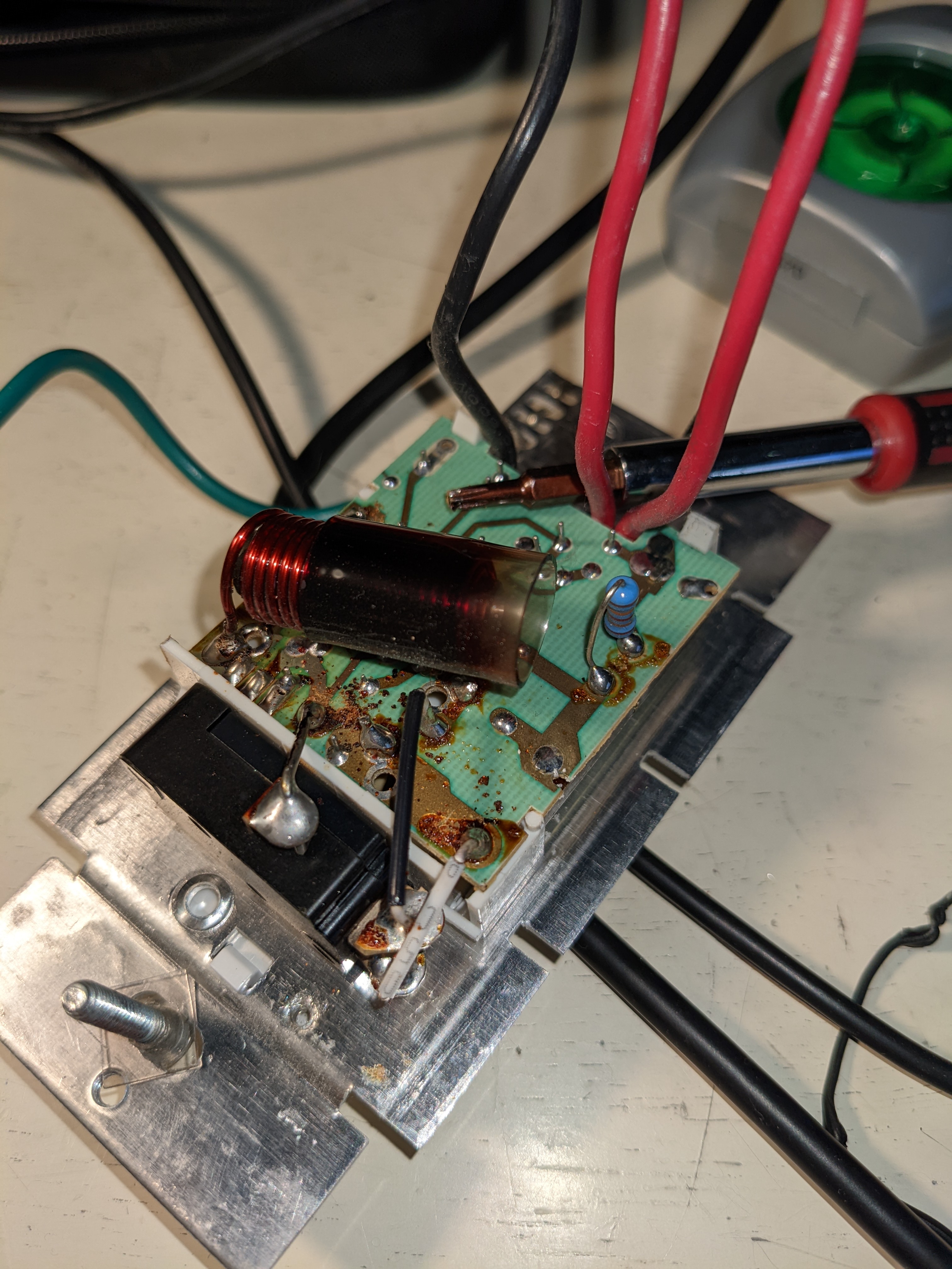
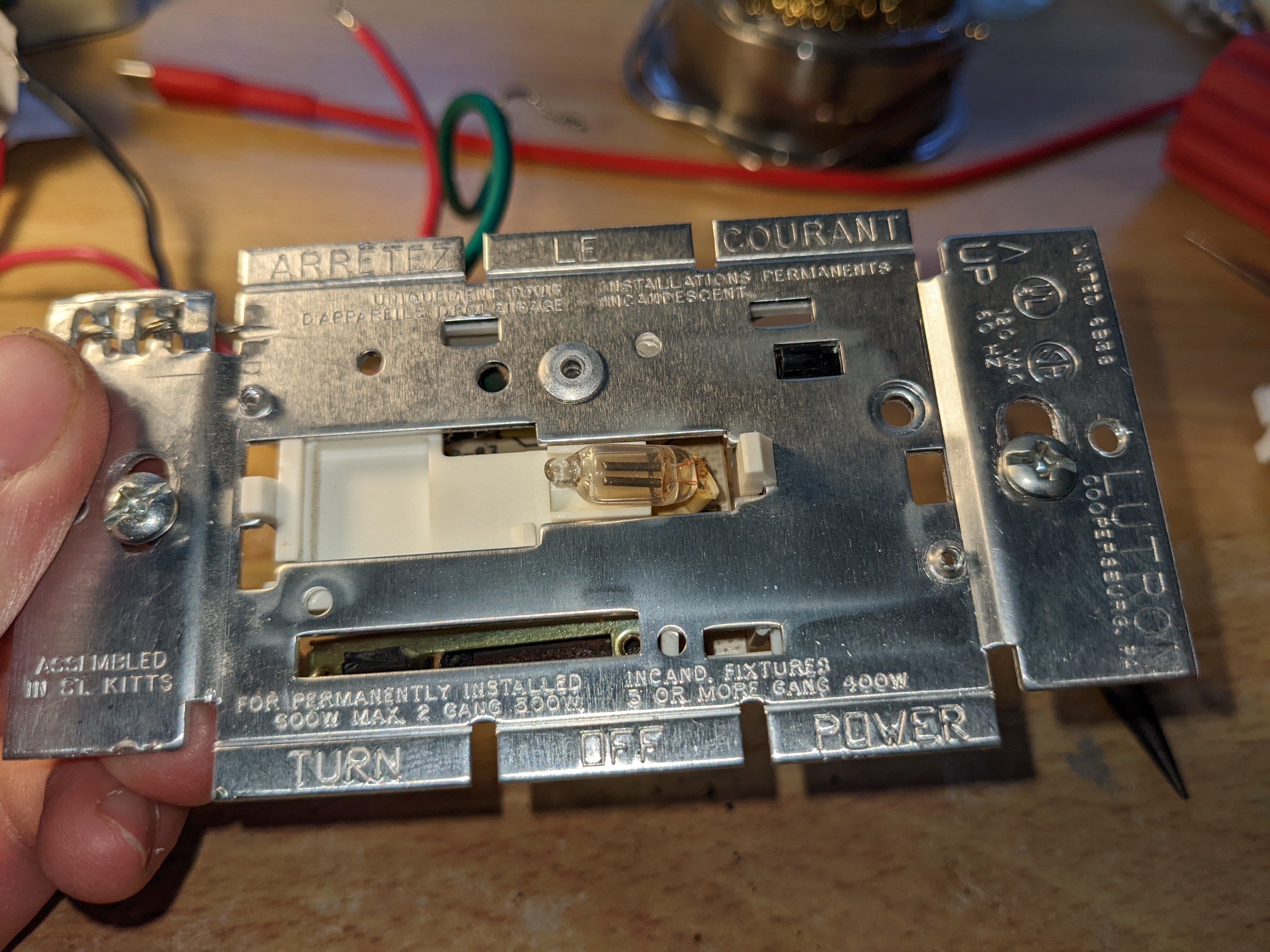
Inspecting the dimmer switch, I discovered it was labeled as an "incandescent dimmer", but now hooked up to 120V LED bulbs. Unscrewing the back of the switch, I found burnt flux residue on the solder joints (whether from soldering or from overheating in use), and blackened plastic around a giant metal coil (indicating overheating?). Prying the PCB away from the metal case and looking underneath, I found a heatsinked transistor-like device (likely a triac) and smaller capacitors under the PCB. This indicated that the switch was a complex active circuit with the potential to radiate RF energy.
Looking online, I found that some incandescent dimmer switches actually cut off part of the AC waveform. Combined with how AC-powered LED bulbs perform their own power rectification and filtering (which means their current draw may not be proportional and in phase with supply voltage), it's easy to see that this could have stressed the dimming circuit into malfunctioning. It's possible that the triac was intended to chop off part of each half-cycle of the AC waveform, but malfunctioned due to design flaws or driving a nonlinear load of LED bulbs, resulting in oscillations123. I thought the interference also occurred when the room lights were off, but I don't remember for sure.
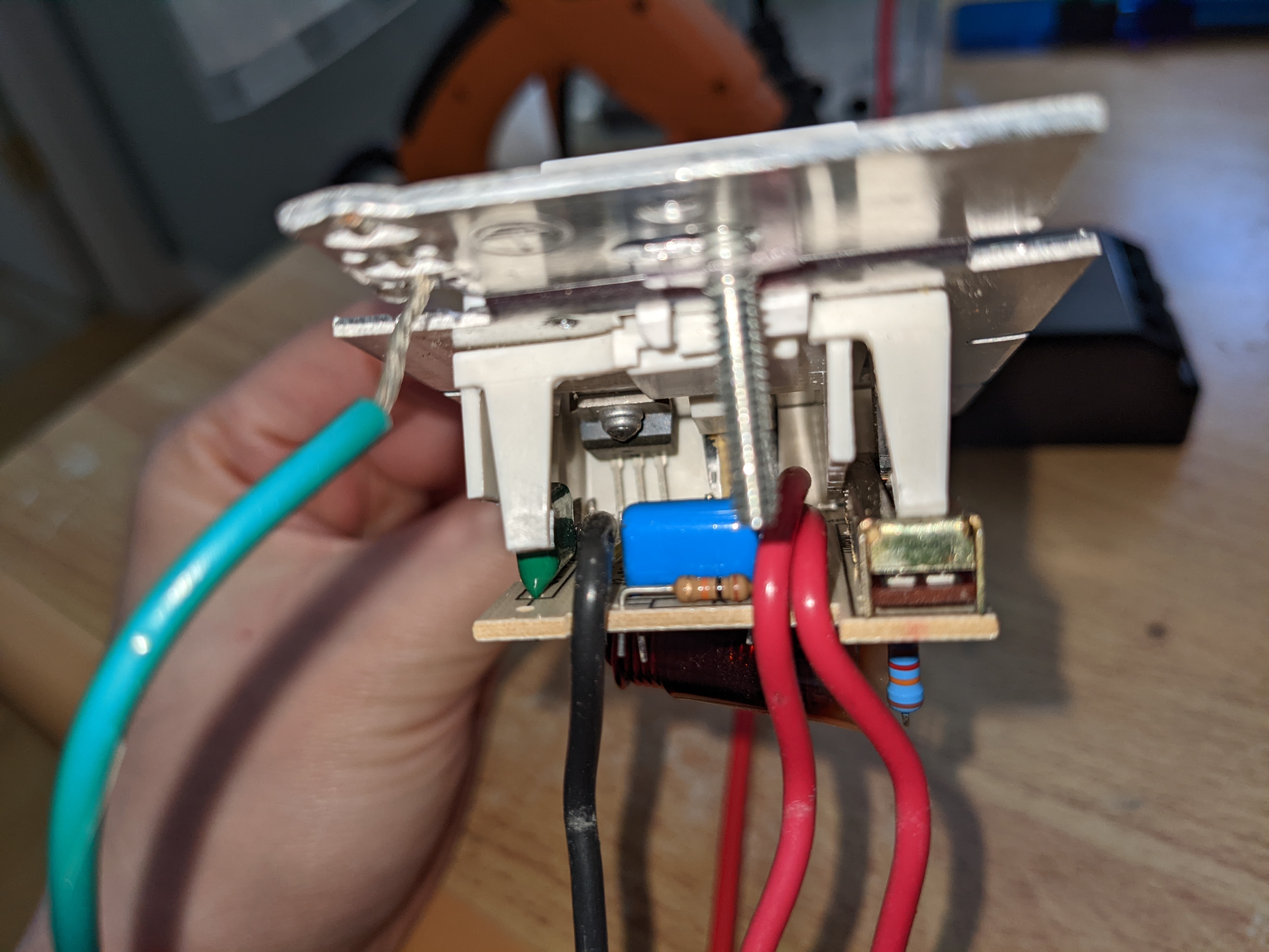
I also found a small neon lamp used to illuminate the switch's face, and I've heard neon bulbs can flicker over time due to wear. However some people have told me that indicator lamps are ballasted by a resistor and unlikely to emit interference. I don't know if it's always illuminated, or only when the ceiling lights are off (I'd turn the lights off to avoid CRT glare while playing games).
Aftermath
After removing the malfunctioning dimmer switch and tearing it apart, I spent a few more days playing games on my Wii. I haven't seen a single instance of full sync loss and a black screen since, but noticed the screen will still occasionally shift vertically for a single frame, often when I plug a GameCube controller into the console.
I've tried adding a ferrite bead around the Wii's AV output cable, then plugging controllers in to trigger an interference spike, but was unable to reproduce a screen flicker with or without the ferrite bead in place. Nonetheless, since adding the ferrite bead I've spent multiple days playing games on and off, and haven't seen the screen flicker once, so I'm hopeful that the static shocks are solved. It's also possible that my debugging changes to the firmware made the GBS-C more vulnerable to losing sync, and the stock firmware is more resilient to sync loss.
Perhaps ideally the video scaler would be more resilient to sync loss and ignore out-of-time sync pulses coming from the input, until there are enough of them that the input has likely changed to a different hsync rate (eg. switching between 480i, 480p, and 720p). This may or may not be possible to implement by editing the GBS-Control's firmware.
Conclusion
I discovered that a malfunctioning light dimmer switch in my wall was likely generating RF interference, causing my Wii to output a garbled video signal to whatever load was present (eg. GBS-C or a 75 ohm RCA terminator). After replacing the light switch, the problem appears fixed. Additionally, I no longer use a very long USB cable on the GBS-C because it may destabilize the ground rail, and added a cooling fan to prevent further thermal damage to the chip (though the fan is loud because it's blowing into a clockgen PCB obstructing airflow, and perhaps running a 12V fan at 5V would be quieter). Now all that's left to do is to find a game I want to play... 💀
Reviewing my notes from the investigation, I'm struck with how many dead ends (researching expensive and ill-suited current clamps, hooking a coaxial cable to two non-ground signals, trying to read non-CSV formats on a PC) and roadblocks I hit along the way, and how much ambiguity I found in my own observations. Many of my scope readings were inconsistent with each other, many had multiple possible explanations, and some were inconsistent with the theories I had at the time. Now I believe that since the sync loss events were triggered by external RF noise from the light switch, this EMI noise could reach all parts of the system at practically the same time and interfere with readings, and since currents could flow through the probes' ground shielding faster than through video cables, attaching oscilloscope probes at multiple places actually interfered with the circuits I was trying to measure. In short, RF is hell, and you're fortunate if you've never had to deal with it.
My original bug report log is at https://github.com/ramapcsx2/gbs-control/issues/461.
Footnotes
"Dimming LEDs with Traditional TRAC Dimmers" (Digikey) mentions that a dimmable LED needs a "dynamic hold circuit" to "prevent the phase dimmer from misfiring".
"Efficient method for interfacing TRIAC dimmers and LEDs" (EE Times) says that triac dimmers produce hard-edged AC waveforms which interfere with LED rectifiers/filtering, and LEDs can cause triacs to misfire if they fail to draw enough current to keep the triac conducting.
"Design Guide for TRIAC Dimmable LED Driver Using FL7730" (Fairchild/onsemi) mentions that LED bulbs can cause dimmers to misfire due to inadequate current, and suffer from spike currents as the capacitors charge quickly when voltage is turned on.