A deep dive into CRT modelines and EDID editing
on
In the process of setting up CRT TVs and monitors, I've often worked with modelines, the cryptic strings of numbers which define how a GPU should drive a display cable with rows of pixels. Once critical to 90's Linux users trying to setup XFree86 to display on their CRT monitors, modelines have found a new life among hobbyists who tinker with resolutions and framerates to bring out the full potential from their CRT and gaming LCD monitors. In this article I'll be exploring the origins and history of modelines, how they're used to hook computers up to CRT displays, and how I wrote a modeline generation tool and discovered multiple bugs in Xorg's cvt tool along the way.
The origins of modelines
CRT timings
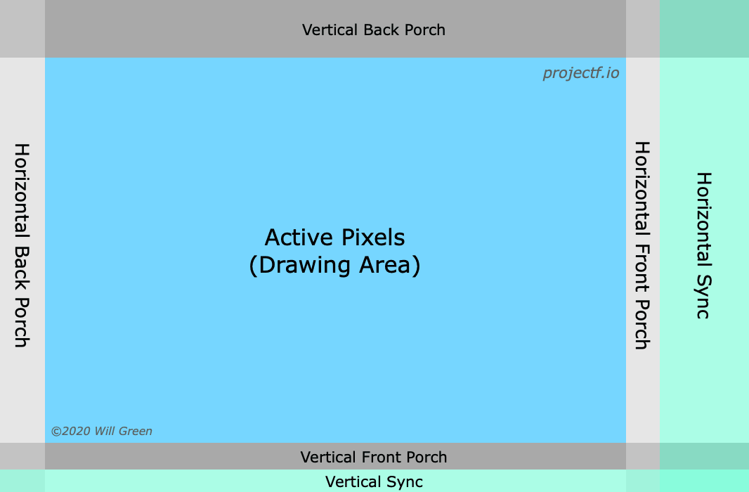
Modelines were originally designed as a way to describe analog display signals between computer graphics cards and CRT monitors. While modern LCD monitors have a fixed array of electronic pixels which can change color, CRTs instead had a continuous screen of phosphors (or on color screens, a fine grid of red, green, and blue phosphors), and an electron beam (or one beam per color) tracing horizontal lines of light across the surface.
The electron beams originate from an electron gun at the back of the CRT, and are aimed using variable electromagnets (deflection coils) which deflect the electrons at an angle. On all consumer displays (not vector displays), the horizontal deflection coils would sweep the beam from left to right before snapping it back to the left, tens of thousands of times per second. The vertical deflection coils would slowly sweep the beam from top to bottom before snapping it back to the top, at a frequency matching the screen's refresh rate (60+ Hz on computer screens). This pattern is known as a raster scan.
The CRT is controlled by a set of signals entering the monitor or television. The video signals control the intensity of the red, green, and blue beams as they move across the screen, modulating the brightness of the colored spot as it scans the image. (Unlike with LCD panels driven by digital display protocols, the display does not actually know how many pixels wide the analog video signal is.) The hsync signal tells the horizontal deflection coils when to sweep the beam back to the left of the display, and the vsync signal tells the vertical deflection coils when to sweep the beam up to the top of the display (while hsync signal pulses continue being sent).
Interestingly, the display signal actually goes black (hblank period) for a specified amount of time before and after the hsync signal is activated. This is because after the hsync signal is activated, it takes time to change the direction that current flows through the horizontal deflection coils, to aim the electron beam to the left. As a result, display signals generally spend a brief period of time in blanking before the hsync signal (front porch duration), and a long time in blanking during the hsync pulse (hsync duration) or after it (back porch duration).
Similarly, the display signal also goes black (vblank period) for multiple whole scanlines before and after the vsync signal is activated. It takes time for the vertical deflection coils to move the beam back to the top of the screen, so display signals spend the majority of the vblank period during or after the vsync pulse (vsync and back porch), rather than before it (front porch).
Sidenote: Analog video connections
How are video and sync signals sent from the computer to a screen? On VGA monitors, there are separate red, green, and blue signal wires, as well as two wires to carry hsync and vsync signals. CRT TV sets used different sync standards; for example, SCART in Europe combined hsync and vsync into one wire (composite sync), which is pulled negative briefly for hsync, and kept negative for most of a line to signal vsync. Component video and older formats would combine sync signals with video (sync-on-luma and sync-on-green), requiring the receiver to interpret positive voltages as video and negative voltages as sync signals. (I've written about how color is encoded over various TV connections in a previous blog post.)
Workstation monitors would often use RGB signals over BNC connectors, with composite sync or sync-on-green rather than VGA's two separate sync lines1.
Modelines in X11
Each CRT display is only made to support a limited range of hsync frequencies (lines per second) and vsync frequencies (frames per second), limiting the resolutions and refresh rates they can display. Some displays would display a black screen or error for out-of-range signals, while others would malfunction (there are stories of monitors physically going up in smoke or flames234)!
Up until the 1990s, displays did not tell computers what resolutions they supported. As a result, to setup a monitor on a Linux/Unix machine, you would have to create a modeline using a modeline prober (like X -probeonly) or calculator5, or look up your monitor in a modeline database6 (like xorg-conf.org?). Then while XFree86 or Xorg (a Unix program which hosts GUI apps and displays them on-screen) was driving your display at a fallback resolution such as 640x480, you'd copy the modeline into your XF86Config or xorg.conf file, then reboot the system (or even apply changes live7) and hope the new resolution would show up correctly. Some users may even have used xvidtune to move the image around their monitor graphically, using an API that predated today's xrandr. (xvidtune still exists and is still optionally shipped with Xorg, but on my amdgpu driver, it's only able to fetch the primary monitor's resolution, but throws an error when trying to set video modes.)
- One source of information about the early days of XF86 setup is the archived XFree86 Video Timings HOWTO from 2000.
- If you have more information about how people configured modelines in the 2000s and earlier, let me know using my email address in the second line of this link.
With the release of EDID in 1994, monitors were now able to report their supported frequencies and resolutions to the computer. Reportedly some people would use tools which requested EDID information from the monitor and generated modelines you had to enter into XF86Config, since XFree86 couldn't yet read EDID data itself. Later, XFree86 4.0 released in 2000 with support for reading EDID information from the monitor and automatically generating valid video modes for the monitor, and this functionality carried over to its successor project Xorg, making manual modeline entry largely obsolete.

Right now I'm visiting my sister for the holidays and Tabata sends a warm purr right back at you.
She misses that monitor though: LCD's are not as comfy as CRT's ;)
Interpreting the numbers
In the past (and today), some Linux users would treat modelines like opaque strings to be used as-is, while others would use tools or manual calculations to understand the meaning of the parameters, then edit or write new modelines to better suit their displays and needs.
An example of a modeline is:
Modeline "640x480_59.94" 25.175 640 656 752 800 480 490 492 525 +HSync +VSyncThe word "Modeline" is followed by a name in quotes, serving to identify this mode to the user. Next comes the pixel clock (megapixels per second).
- In the past, some GPUs could only output a limited set of pixel clocks8, limiting what modelines could be used.
- Interestingly, the GBS-Control's TV5725 chip also only has a fixed set of output dot clocks. This makes it difficult to create a full-width supersampled 480p output mode (since 81 MHz pixel clock produces a too-narrow output, and 64.8 MHz pixel clock produces a too-wide output). Outputting the correct width (640/800) requires you to enable horizontal scaling (which causes high-frequency aliasing), change the input sampling rate (which may cause aliasing and requires reconfiguring the input PLL that I haven't figured out), or change the output dot clock (which requires an external clock generator not everyone has installed).
Inspecting the horizontal timings, 640 656 752 800 means that each scanline begins displaying image pixels at time 0, and stops displaying video 640 pixels later (meaning the image is 640 pixels wide). At time 656 (pixels) the horizontal sync pulse begins, at time 752 (pixels) the horizontal sync pulse ends, and at time 800 the GPU begins outputting pixel 0 of the next scanline.
- We can deduce that during each scanline, the GPU spends 4/5 of the time outputting video and 1/5 in blanking, emits a hsync pulse 16 pixels after the active video pixels end, and spends the rest of the scanline waiting for the electron beam to move to the left of the image again.
Inspecting the vertical timings, 480 490 492 525 means that each frame begins displaying image scanlines at line 0, and stops displaying video 480 lines later (meaning the image is 480 input pixels and output scanlines tall). At time 490 (lines) the vertical sync pulse begins, at time 492 (lines) the vertical sync pulse ends, and at time 525 (lines) the GPU begins outputting line 0 of the next frame.
- The GPU spends about 91% of the time outputting image scanlines and 9% in vertical blanking, emits a vsync pulse 10 lines after the video lines end, and spends the rest of the frame waiting for the electron beam to move to the top of the screen.
+HSync and +VSync mean the horizontal and vertical sync lines are normally low (grounded), and get pulled to high voltage (3.3 to 5 volts) to signal a sync pulse910 (active-high). If the modeline contained -HSync or -VSync, the corresponding wire would be normally held at a high voltage and only pulled to ground during a sync pulse (active-low).
- Note that standard/DMT 640x480@60 normally has active-low hsync and vsync (
-HSync -VSync), but HDMI's CEA-861 resolution has positive sync pulses (as shown here).
VSync pulse timing within a scanline
What's the exact time the vsync pulse begins and ends relative to scanlines' hsync pulses, and non-vblank scanlines' horizontal display/blanking periods? This turns out to be a surprisingly complex question.
- The official HDMI 1.3 spec has a diagram of the video signal (page 72). In HDMI, each scanline begins when hblank starts and ends when hactive ends (unlike X11 modelines where timings begin with active and end with blanking), and the vsync pulse begins and ends on scanline boundaries. This means that the vsync signal starts and stops when the preceding hblank period starts, a partial line earlier than what the modeline indicates.
- Note that you can't actually see hblank start when the vsync pulse starts or stops, because the vsync pulse is surrounded by vblank (unless you have vertical porches 0 scanlines tall), which is transmitted the same way as hblank. You can still calculate the time hblank would start without vblank, by adding multiples of htotal to previous hblank start times.
- Also it doesn't matter when vblank starts or stops, since it always starts/stops during or next to hblank and both types of blanking are transmitted the same way.
- The PicoDVI code matches the HDMI diagram; it toggles vsync on the horizontal front porch of the previous scanline, before hsync starts or stops.
- I do not have a logic analyzer to verify that valid GPU-generated HDMI signals begin vsync not when hsync is asserted, but earlier when hblank begins relative to hsync.
- Note that you can't actually see hblank start when the vsync pulse starts or stops, because the vsync pulse is surrounded by vblank (unless you have vertical porches 0 scanlines tall), which is transmitted the same way as hblank. You can still calculate the time hblank would start without vblank, by adding multiples of htotal to previous hblank start times.
- Interestingly, I found that VGA uses a different convention for vertical sync placement; the vsync pulse starts and stops when the hsync pulse starts, just before (X11) or slightly after (HDMI) the vsync start/stop scanline begins. This lies in between the HDMI spec and X11 modelines.
- After ordering a VGA splitter cable and constructing a VGA video/vsync to RCA rig, I began plugging various devices with VGA outputs into my motherboard's 192khz audio interface, and recording the video and vsync signals using Audacity.
- Probing my Plugable DP-to-VGA adapter (Realtek RTD2166 chip) and testing various modelines with hsync starting and stopping earlier and later, I found that vsync pulses arrive slightly before the previous hsync pulse starts, and end when the previous hsync pulse starts. (source)
- Probing my Dell Inspiron 15R SE (7520) laptop with HD Graphics 4000, Intel Ivy Bridge chipset, and built-in VGA output, and varying the hsync timing and width, I found similar results. The vsync pulses started and stopped on the preceding scanline's hsync pulse starting time (or slightly afterwards, possibly because my voltage attenuator acted as a delaying low-pass filter). (source)
- I got the same results on a Vostro 1400 laptop with Core 2 Duo CPU and GMA 965 chipset graphics. (source)
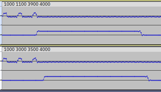
In this screenshot, I constructed two custom modelines (60.72 1000 _ _ 4000 240 240 247 253 -hsync +vsync) on my 15R SE laptop, with hactive taking up 25% of each scanline, and hblank or sync taking up the remaining 75%. Then I recorded the VGA cable's green pin on the left channel (active/blanking intervals), and the vsync pin through an attenuator on the right channel (vsync pulses). In the top recording, I started the hsync pulse at the start of hblank, and in the bottom recording, I started the hsync pulse near the end of hblank. I found that delaying the hsync start time delays vsync start/stop as well.
- DVI-I connectors have both analog (VGA-like) and digital (DVI/HDMI-like) output pins. The replies at https://superuser.com/q/1519352 claim that GPUs only activate one of the two sets of pins at a time, so presumably the vsync timing depends on which output is active. We do not speak of the thin clients which send independent VGA and DVI signals to two displays through a single DVI-I port.
- DisplayPort (spec) doesn't stream pixels in real time like VGA and HDMI, but instead uses a fixed-rate transmission bus which interleaves packed pixels (micro-packets or transfer units), blanking start/stop markers, and extra data. If the rate of pixels is lower than the DP signal's transfer speed, the DP source fills extra space in pixel packets with "stuffing dummy data symbols" surrounded with
FSandFEsymbols.- DP transmits
BSandBEsymbols when horizontal/vertical blanking starts or ends, with a VB-ID packet (indicating whether it's hblank or vblank)11, stuffing symbols, or other data packets (eg. audio) in between. Unlike HDMI it does not transmit a new blanking symbol for each pixel of blanking requested by the modeline, nor does it transmit symbols for when sync pulses start or stop. Instead, modeline timings are transmitted as metadata in the "Main Stream Attribute" packet sent once per frame. - These properties mean that a DP-to-VGA/HDMI converter cannot merely output pixels in sync with the input symbols being received, but must buffer pixels across packets and synthesize blanking durations and sync pulses based on the timing metadata. As a result, the concept of "vsync pulse position relative to hsync pulse" is somewhat irrelevant to the actual protocol, and more a property of the DP-to-VGA converter.
- The "Main Stream Attribute" timing metadata (page 74) stores the active size (resolution) and total size (modeline totals) of the frame. It also stores the sync pulse widths, and the time active video starts relative to the time the sync pulse starts. This means that scanlines and frames by convention begin on h/vsync pulse begin; this matches how VGA's vsync pulses begin/end on hsync pulse begin, but does not match HDMI timings or X11 modelines.
- In interlaced signals (page 76+), "Main Stream Attribute" stores the timings of the top field, which contains the first active line of a frame. The specification's diagrams show that the top field is preceded by a hsync-aligned vsync pulse (meaning the total front porch across two fields is 2n+0.5), though I don't know if this is required. For details on interlacing, see below.
- DP transmits
(Sidenote: I've written about probing VGA signals in another article.)
Getting a VGA output
CRT monitors are analog displays, and generally came with a VGA input port rather than today's more common HDMI and DisplayPort. As a result, to connect a CRT to a modern PC and GPU, you will usually need a DAC adapter or older graphics card with native analog output.
900-series and older NVIDIA cards came with VGA or DVI-I ports with native analog RGBHV video output, as did AMD's 300-series and older cards.
If you want to render games on a newer GPU, you can install a modern NVIDIA GPU, render games there, and have it stream frames to an older AMD card with analog out (for example a HD 5450 which is otherwise worthless as anything beyond a low-spec display adapter).
- This can be done using Windows 10's "Graphics preference" screen or RetroArch's options. I found a video saying that you get around 3 milliseconds of latency when passing 1920x1440 video frames between GPUs over a PCIe 3.0 x8 bus.
- I suspect that if you're using double-buffered (frame-locked) vsync, the latency will be folded into the vsync latency, unless it causes you to go over your frame time budget (halving your FPS).
- The video also says that OpenGL games did not work properly in GPU passthrough, whereas DX11, DX12, and Vulkan worked fine.
- To get BIOS-era graphics cards (like a HD 5450) to boot on modern UEFI motherboards, you will have to enable CSM in your BIOS settings (disable pure UEFI mode).
- On Windows, it's generally a bad idea to install an older AMD GPU (for analog output) along with a new AMD GPU (for rendering), since you have to use older AMD drivers which support the older card, which may not support the new card with optimal performance (or at all).
- I've tried installing the latest AMD drivers and control center for my RX 570, along with older AMD drivers for a HD 5450 by hand using the .inf files. This broke the AMD Settings app that came with my new drivers. Also my wallpaper and Dolphin rendered incorrectly and dropped frames on my old GPU's display outputs (video). I ended up wiping my drivers with DDU and removing the HD 5450 from my system.
Alternatively you can install a newer GPU, and hook up a HDMI or DVI output to a DAC. There are many different DACs to choose from, with different power supply stability, image bandwidth, and feature sets, falling into two main categories (HDMI vs. DP).
- Some people recommend DP-to-VGA adapters because good ones have better bandwidth than the best HDMI-to-VGA adapters. There are cheap and easily-available DP-to-VGA dongles, like my Plugable RTD2166 (B01GW8FV7U) or a CableDeconn, which are more reliable and have more predictable color reproduction (full range RGB) than cheap HDMI-to-VGA dongles. The StarTech DP2VGAHD20 is more expensive but supports higher pixel clocks.
- I've had bad experiences with cheap HDMI-to-VGA dongles. The one I got off Amazon was not detected at all on one laptop (even when powered externally), and on my other machines, every few minutes it would vanish from Windows and drop the output signal. Also the output voltage was zero for all HDMI RGB pixel values from 0 to 16 (causing black crush). If you set your GPU to output limited-range RGB to the dongle, it would fix black crush (at the cost of reducing peak brightness), but would not fix the dongle dying every few minutes.
- A Reddit thread claims that you can fix dying HDMI DACs by removing Pin 12 from the VGA cable it's connected to, cutting the EDID signal. This prevents the DAC from asking the monitor what resolutions it supports. From here you could either use default Windows resolutions, or use CRU (with either the real or fake EDID as a starting point) to add resolutions you want.
- I was unable to test this fix as I have already returned my DAC to Amazon. Also I'd prefer to cut the PCB trace on the defective DAC, rather than pulling a pin out of a working VGA cable I might want to use elsewhere.
- In fact, I want to cut the DAC chip's I2C input/output traces entirely, and instead wire the HDMI cable's I2C lines directly to the VGA port's lines (leaving the chip's pull-up resistors connected to the chip rather than the VGA port).
- Some people recommend Tendak's monitor-side HDMI-to-VGA dongles (Amazon B01B7CEOVK) because they do not have black crush. Unfortunately I've heard on Discord that Tendak is a "chip lottery", with occasional reports of crushed blacks. A Redditor says "Tendak adapters make use of a number of different ICs. Some of them look really good, and others have black crush. There's absolutely no way to know which chip you are buying without opening it up and checking."
- The MiSTer community has compiled a guide to HDMI-to-VGA adapters (for FPGA, but much of the knowledge is transferrable to PCs). It states that the AG6200/AG6201 is a common HDMI-to-VGA DAC which suffers from black crush. I don't know if the dongle I returned had that chip.
- A Reddit thread claims that you can fix dying HDMI DACs by removing Pin 12 from the VGA cable it's connected to, cutting the EDID signal. This prevents the DAC from asking the monitor what resolutions it supports. From here you could either use default Windows resolutions, or use CRU (with either the real or fake EDID as a starting point) to add resolutions you want.
- Many laptops lack DP outputs altogether. You may decide to buy an adapter based on whether your GPU has more spare HDMI or DP outputs not in use.
- If you want to use interlacing on a monitor, you should probably buy a HDMI-to-VGA adapter. If you're running Windows, you cannot enable interlacing on DP ports with AMD or NVIDIA GPUs, but only Intel iGPU motherboards (if they even have DP ports).
Getting correct colors over VGA
Digital-to-VGA DACs can suffer from various nonlinearities and inconsistencies in their color output:
- Many DACs (both Intel integrated graphics and DP-to-VGA DACs, not sure about GPUs or HDMI-to-VGA) exhibit noticeable noise at some resolutions, often with a frequency bandwidth similar to the hsync rate (much lower than the pixel clock). This is visible as random horizontal banding across the image which jumps around randomly like TV static (but is much wider).
- As mentioned before, AG6200/AG6201-based HDMI-to-VGA dacs suffer from black crush, where RGB values ≤ 16 are converted to black output. This is to better handle limited range RGB inputs (where black is encoded as RGB 16 rather than 0), but with full-range RGB inputs it causes dark areas of images to look black and lose detail.
- Some DACs convert RGB values to voltages in a nonlinear way, resulting in incorrect gray ramps and color reproduction. Others may convert white colors into voltages above or below the correct VGA peak level of 700 mV (which can result in clipping on-screen), or have inconsistent brightnesses between the 3 color channels (which results in color casts on-screen).
The MiSTer FPGA community has compiled a spreadsheet where they tested VGA DACs for black crush/linearity, peak voltage, and color balance.
Warning for DP-to-VGA on AMD graphics: When plugging a Plugable RTD2166 DP-to-VGA DAC dongle into an AMD GPU (in my case a RX 570), the display may show wildly inaccurate colors. In my case, reds were noticeably amplified, giving the entire screen a reddish cast except for white colors (where the red channel was clipping at full scale). The colors were correct when plugging the same DAC dongle into an Intel Ivy Bridge desktop computer using integrated graphics (on a Z77X-UD3H motherboard) with a DisplayPort output.
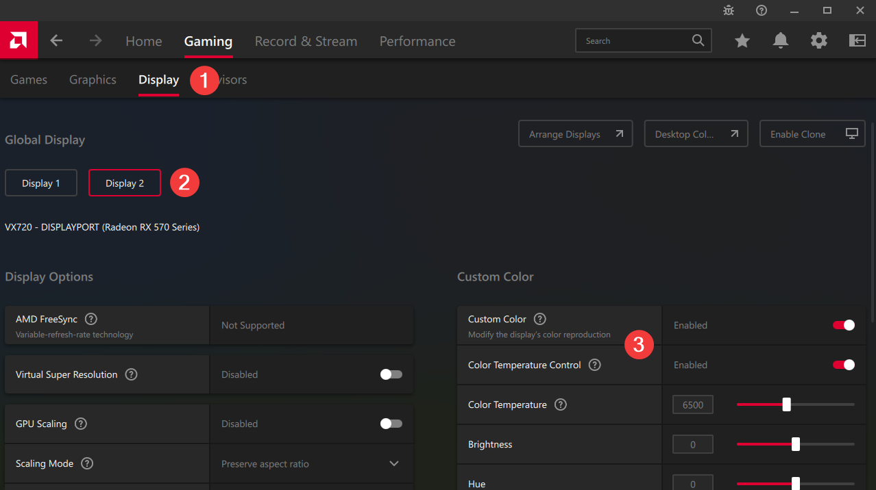
To fix this problem, I found I had to open AMD Software and click on tabs Gaming → Display, then pick my CRT monitor (eg. Display 2), and disable Custom Color altogether.
Strangely enough, after I uninstalled AMD drivers with DDU and reinstalled the drivers, disabling Custom Color did not fix the red color cast! Instead I had to enable Custom Color and Color Temperature Control, then set Color Temperature to 6500K. (IIRC this temperature previously did not result in a correct color appearance?) This time around, I validated using an oscilloscope that all input RGB color values up to 255 produced distinct red voltages and were not clipped. I also verified that other color temperatures (like 6400K and 6600K) produced clipped reds.
- If you encounter a color cast when using a DP-to-VGA dongle with an AMD GPU on Windows, try disabling Custom Color. If that does not work, try enabling Custom Color and then enabling Color Temperature Control (and leaving Color Temperature at 6500K).
- To check if light gray is displayed with the same shade as white, you can show a black-to-white gradient, or window shadows on a white background. Unfortunately it's very difficult to identify small errors by eye.
Finding a CRT modeline
If you find yourself wanting a modeline today, to make a display run at a resolution and refresh rate your OS normally doesn't expose, there are many ways you can get one.
If talking to a television, you can find SDTV modelines at https://geocities.ws/podernixie/htpc/modes-en.html, or more TV/monitor modelines at https://www.mythtv.org/wiki/Modeline_Database. There are also tools to generate modes or program your graphics card to a specific mode; AdvanceMAME claims to support creating video modes matching specific consoles, but I've never tried using it to play any specific consoles, and I'm not sure it has a generic tool.
If talking to a VGA computer monitor, there are better-developed tools to generate modelines. There are actually many different types of modelines:
- DMT (Discrete Monitor Timings) is a set of industry-standard/VESA-defined timings for monitors. These are widely supported among CRTs, but if you need a resolution and refresh rate not found in the set, you'll have to use a formula.
- GTF (Generalized Timing Formula) is a formula used to calculate timings for an arbitrary resolution and refresh rate. Some people say it may produce better geometry than CVT on older CRTs.
- CVT (Coordinated Video Timings) is a newer formula that produces slightly different timings. It also comes with reduced-blanking variations intended for LCDs, including the recent CVT-RB3 intended for FreeSync monitors.
If you want to generate a modeline, you have many tools to choose from:
- https://arachnoid.com/modelines/index.html generates GTF timings/modelines.
- https://tomverbeure.github.io/video_timings_calculator can generate many forms of timing, including DMT, CEA-861 (HDMI television timings), and CVT.
- Note that the generated DMT modelines are incorrect for 640x480@60, as it fails to account for border pixels as either active or blanking times. The timing table is still "accurate" (except that it omits border pixels altogether).
- This calculator also generates incorrect interlaced VGA modelines, though interlacing will be discussed later.
- You also have Linux command-line tools like
gtfandcvt, oredid-decode --dmt/gtf/cvt/....- Note that
cvthad multiple bugs resulting in incorrect timings being output. I've reported and fixed most of them at the FreeDesktop Gitlab (hsync start fix, back porch fix, interlacing bug), and the fixes should be released at some point.
- Note that
To install custom modes, you will either generate a patched EDID binary (on most OSes), or install custom resolutions to the system in addition to the monitor's EDID (Linux X11 xrandr, some Wayland compositors).
Reading a monitor's native EDID and modes
Before adding custom resolutions, you may want to extract your display's original EDID to a file.
- On Windows you can use tools like CRU and EDWriter. Note that you can skip saving a file if you're using CRU to override resolutions on Windows.
- On Linux you can use
xrandr --verboseand parse the hexdump, or grab the files directly from/sys/class/drm/card1/*/edid.- Alternatively after you run
sudo modprobe i2c-devandi2cdetect -lto get interface numbers, you can talk to monitors directly over I2C using get-edid,i2cdump -y (bus id) 0x50 [i], or my write-edid tool. - You need to use
i2c-devif you want to use dedicated I2C hardware (like rp2040-i2c-interface on a Pi Pico) to talk to a monitor or standalone EEPROM, rather than have the GPU fetch EDID from a connected display.
- Alternatively after you run
Note that some tools will dump 256 bytes of EDID data, even on monitors which only have a 128-byte ROM. You can open the file in a hex editor, check if the second half is all FF or identical to the first half, and delete it if so.
Warning: DP-to-VGA adapters based on the RTD2166 can edit the EDID data being read from the monitor, even when you are not using custom resolutions! The dongle will alter or replace any resolutions with a pixel clock above the chip's limit of 180 MHz (from 2 lanes of DP HBR). On my Gateway VX720, it replaced the native resolution (the first detailed timing descriptor) of 1600x1200@75, with 1024x768@60 DMT but with the wrong sync polarities (both active-high). This caused my monitor to not properly recognize the resolution as 1024x768, and fail to save position information properly.
- By flashing custom EDIDs to an EEPROM, I found that 1600x1200@75 gets replaced with 1024x768@60 (with active-high sync, regardless of the original resolution's sync polarity).
- The RTD2166 does not replace out-of-range resolutions (like 1600x1200@75) in CTA-861 extension blocks. It still cannot display them though.
- When outputting 1024x768@60, Windows, macOS, and Linux Wayland used the incorrect sync polarities, while Linux X11 ignored the EDID and used the correct active-low sync pulses.
- Regardless of your operating system, dumping EDID data through a RTD2166 DP-to-VGA will produce incorrect contents.
Workarounds for incorrect modes
If you are affected by a RTD2166 returning incorrect resolutions, you can bypass the incorrect resolution by installing an EDID override to your OS. The default resolution can be 1024x768@60 with correct sync polarities (both active-low), or another resolution altogether (so the computer will use default correct timings for 1024x768@60).
- To avoid other unwanted changes to EDID parameters (like standard timings and sync/features), I recommend taking a clean EDID capture using an older computer/GPU with a native VGA port (tested on Ivy Bridge using Windows CRU and Linux xrandr), or rp2040-i2c-interface on a Pi Pico using Linux tools (tested using get-edid and write-edid).
- Note that some newer laptops use an internal RTD2166 to expose a VGA port, which may also corrupt the EDID.
- Afterwards you can either keep or remove resolutions at too high of a pixel clock. On Windows with AMD drivers, even when I applied the unmodified 1600x1200@75 EDID using CRU, Windows refused to output this resolution through the dongle (because the resolution had too high of a pixel clock for the DP HBR link).
If you are plugging a VGA EDID emulator dongle (with an I2C EEPROM) into a RTD2166, you can flash the EDID override to the EEPROM, but all detailed resolutions must be valid (with pixel clock below 180 MHz). I found that both 1280x960@75 and 1024x768@60 were passed through unmodified.
Managing custom modes on Windows
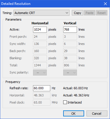
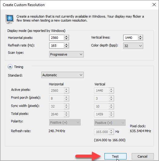
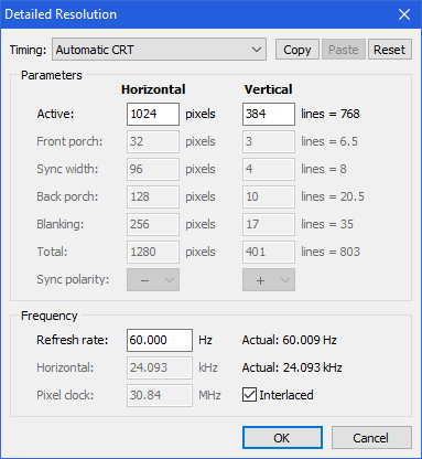
Custom Resolution Utility (CRU) is compatible with all GPU vendors. To use it to add a custom resolution, first run CRU.exe, pick a monitor on top, then under "Detailed resolutions", click "Add...". In the new dialog, you will have many ways to pick a resolution and enter/generate timings (CRU docs):
- Automatic CRT - Uses standards compatible with CRT monitors. Uses VESA DMT for 4:3/5:4 resolutions, CVT otherwise.
- CVT standard - Standard intended for CRT monitors.
- GTF standard - Old standard commonly used with CRT monitors.
Once you're done, run restart64.exe and wait 20 or so seconds 🙁 for the GPU drivers to restart and Windows to see the newly added resolutions.
- After adding and switching to a new mode on Windows, you'll have to tune your CRT monitor's geometry controls to center and fill the picture in your screen.
- If the picture has linearity problems (or you're on a TV without geometry controls), you may have to switch between DMT, CVT, and GTF timings, or tweak the modeline parameters manually until you find something that works well.
- To improve horizontal linearity, you can move horizontal blanking between front/back porch (move the hsync pulse relative to hactive), or increase the horizontal blanking time (at the cost of increased pixel clock and blur).
- To reduce the pixel clock (reduce blur), you can reduce horizontal or vertical blanking intervals (porches and sync pulses).
- If you run out of detailed resolution slots (by filling 3 slots, or 4 slots and removing the monitor name), you can add an extension block (expanding the EDID to 256 bytes) which can hold several more resolutions:
- CTA-861 blocks have the broadest support among EDID editors. They originate from the HDMI standard, but also work on VGA and DP ports. Be sure to not accidentally enable underscan!
- DisplayID 1.3 blocks originate from DP, and are supported by CRU and AW EDID Editor (but not hex editors like 010editor, or some EDID decoders). Annoyingly, the resolution list is buried two dialogs deep in CRU.
On AMD GPUs, "AMD Software" also allows editing custom resolutions. It has the advantage that you don't need to wait as long to apply resolutions. But I found the resolution calculator dialog to be janky, and others have recommended avoiding it altogether in favor of CRU.
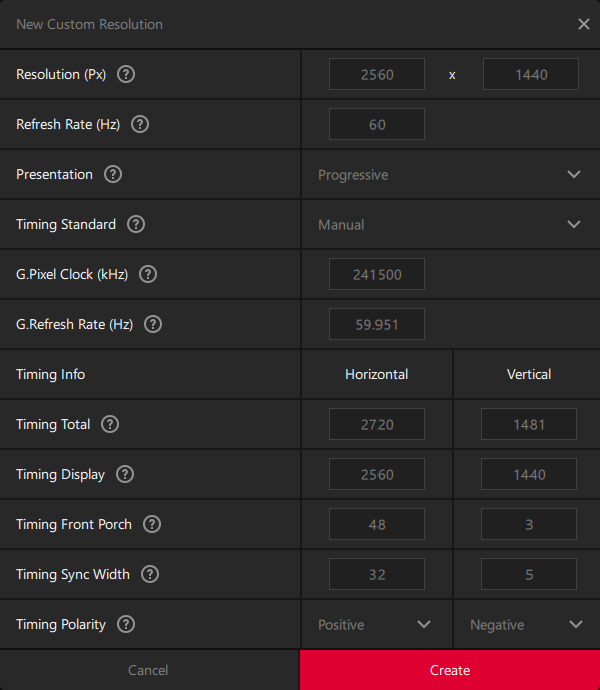
- If you press Tab to switch text fields and then type a new number, it appends to the existing content, rather than selecting the contents and replacing it when you type.
- If you enter a resolution with no DMT timings, switching the timing standard to DMT keeps the previously calculated (non-DMT) timings. Instead the DMT mode should be grayed out, or picking it should replace output timings with a "missing DMT mode" error.
- If you pick DMT timings, switching to non-DMT resolutions keeps the previous (incorrect resolution) timings. It should switch the mode to Manual, or print a "missing DMT mode" error.
- Clicking the "Refresh Rate (Hz)" textbox always exits DMT mode, even if you leave it unchanged or type a valid DMT refresh rate for the current resolution. (It also changes "G.Pixel Clock (kHz)" slightly, but oddly not "G.Refresh Rate (Hz)".)
- Worse yet, clicking the refresh rate also switches from CVT to Manual timing standard, even though CVT supports arbitrary refresh rates!
- Confusingly you can also edit the output "G.Refresh Rate (Hz)" separately from Refresh Rate. I'm not sure what's the use of this, perhaps the "actual refresh rate" derived from the pixel clock and timing totals, which can deviate from your requested rate?
I do not have a NVIDIA GPU to test its custom resolution editor, but have asked people online for advice on how to use NVIDIA Control Panel:
Anyway, NVCP is usually fine as long as the user is aware that "Automatic" timing presets is almost never what they want to use.
Automatic in NVCP basically tends to assume you want to scale everything to super standardized resolutions like 1080p, or 1600x1200 etc. so you'll just get a bunch of ugly GPU scaling for no reason and fixed refresh rates.
The best way around that is to simply pick GTF or vanilla CVT.
On Intel integrated graphics, the driver differs by generation; 5th gen and older CPUs use Intel Graphics Control Panel, 6th gen and newer requires Microsoft Store and Intel Graphics Command Center (I cannot test this on Windows 10 Ameliorated), and Arc GPUs (and possibly 11th-13th gen CPU integrated graphics) require Arc Control Software.
Unfortunately, Ivy Bridge and older GPUs ignore all EDID overrides installed by CRU.
- On Ivy Bridge, you can right-click the desktop to access the driver's custom resolution editor. But this editor is worthless, as it erroneously uses the back porch width for both front and back porch timings.
- Instead, you have to use CRU to build timings, then export and run a .exe file. (I don't know why CRU can't do that automatically when you press OK.)
- Another issue is that, with the exception of low resolutions like 640x480@60, Ivy Bridge's VGA output only supports dot clocks which are a multiple of 1.5 MHz. Other modes are sped up or slowed down to the closest multiple of 1.5 MHz, altering their refresh rates. To get the correct frame rate out, you have to create custom modelines and alter their horizontal/vertical blanking to bring the dot clock to around a multiple of 1.5 MHz.
Output resolution not matching desktop resolution
One footgun is that if you pick a resolution and refresh rate that Windows doesn't know how to display (because it lacks a CRT mode), it may set the desktop resolution to your request, but pick a different larger display signal resolution than you selected, and upscale the desktop to the display resolution. This happens on both Windows 7 and 10, and results in a fuzzy image or missing scanlines on-screen. On Windows 10, you can check if this is happening by opening "Advanced display settings" and checking if "Active signal resolution" does not match the "Desktop resolution" that you have selected.
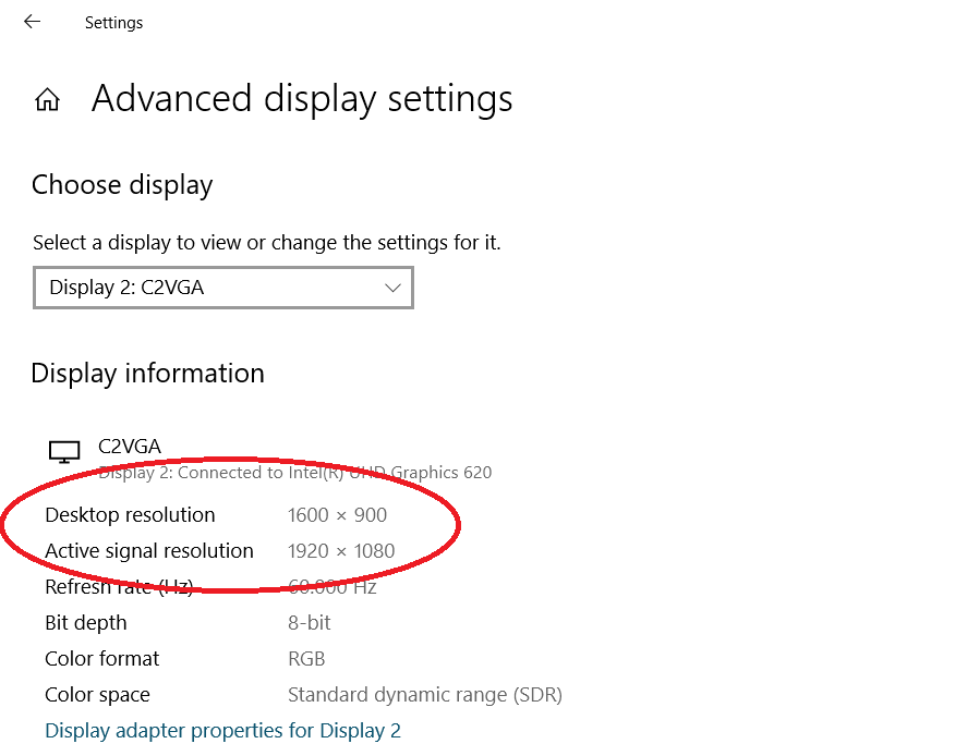
To prevent this from happening, try changing the "Refresh Rate" on the same page until "Active signal resolution" changes to match. If that still doesn't work, try clicking "Display adapter properties for Display #", then in the dialog "List All Modes", pick a desired mode, then click OK twice. Hopefully that should fix the problem.
Unfortunately, on Ivy Bridge HD 4000 integrated graphics with Windows 7, even "List All Modes" does not natively output resolutions below the monitor's "default" resolution (the first detailed resolution in the EDID), but instead scales the desktop to the default resolution.
- To prevent this issue from happening, you can use CRU (and export a .exe file) to replace the first detailed resolution with 640x480@60. Now every resolution you pick in "List All Modes" will output the signal natively, since it's above the monitor's "default" resolution of 640x480@60.
- As a more tedious alternative, after switching resolutions you can force the display output to match the desktop resolution. To do this, right-click the desktop -> "Graphics Properties...", in the new window click Display, pick your CRT from the dropdown, then set "Scaling" to "Maintain Display Scaling".
- As a shortcut, you can right-click the desktop -> "Graphics Options" -> "Panel Fit", pick the CRT (it's harder to pick the right monitor because the right-click menu only shows the type of display and not the monitor name), then click "Maintain Display Scaling" as before.
- The downside to this approach is that you will have to reapply "Maintain Display Scaling" every time you switch to any resolution below the monitor's "default" resolution.
Managing custom modelines on Linux with auto-modeline
If you want to apply custom modelines on Linux X11, you have to first obtain the modeline (by looking up a modeline calculator or running gtf or cvt in a terminal), then run three separate xrandr invocations to create the custom mode (xrandr --newmode name ...), then add it to a display (xrandr --addmode output name) and set the display to the mode (xrandr --output output --mode name).
Then if you want to change the mode (for example switching between different blanking and sync sizes, or between DMT or CVT), you have to repeat all these steps with a new name (since you can't edit a mode in place). If you want to uninstall the old resolution, you'd then call xrandr --delmode output name followed by xrandr --rmmode name.
All these steps are necessary because xrandr and the Xorg server have many limitations on mode management:
- You cannot set an output to a mode unless you've installed the mode to that display.
- You cannot alter a mode which exists, unless you delete it first.
- You cannot delete a mode from an output if the output is currently displaying that mode.
- You cannot remove a mode from the system if it's installed on an output, even if the output is inactive or using a different mode.
To automate creating and switching modes, I've written a program auto-modeline which automatically generates modelines based on specifications (dmt/cvt, width, height, fps).
- By running
auto-modeline print cvt 1280 960 60, it can take the place of thecvtprogram (with the bugs already caught and fixed). If you replacecvtwithdmt, it will print out the matching DMT timing (if it exists), based on a locally saved database instead of having to visit https://tomverbeure.github.io/video_timings_calculator. - Running
auto-modeline editwill createmodelines.ini, which defines the resolutions enabled for each display, and open it in a text editor. If you add mode specifications (eg.cvt/dmt width height fps), then runauto-modeline, it will automatically calculate the correct resolution modes, add them to the system with auto-generated unique names, install each mode to the correct monitors, then print the resulting list of modes per monitor.- If you run
auto-modeline (display), it will only print the names of custom modes enabled on that display. - Then you can run
auto-modeline (display) (name)to activate that monitor to a specified mode.
- If you run
- To alter the list of active modes, you can edit
modelines.inito add or remove modes, then runauto-modelineoptionally with(display) (name). This will automatically add and install modes added to the file, uninstall and remove old modes no longer present in the file, and switch the display to the specified mode if desired. - If you want to try a resolution without editing a file, you can run
auto-modeline apply (output) (spec), which allows previewing a resolution from the command line directly, without even having to editmodelines.ini!
There are multiple ways to define a mode in modelines.ini or auto-modeline print/apply:
-
cvtordmtfollowed bywidth height fpswill automatically generate timings based on the resolution you specify.cvtaccepts any resolution and FPS, whiledmtrequires that your specified resolution exists in a pre-defined list of resolutions (the program will error out if it's missing).- Technically you can use
ceaas well to pick from predefined HDMI modes, but many modes are inaccessible because they have fractional frame rates like 59.94, and my program filters these entries out currently (since it only supports user requests for integer FPS). gtfis not currently supported, and may be added in the future.
-
customfollowed by"name" pixel-mhz hdisplay hsync_start hsync_end htotal vdisplay vsync_start vsync_end vtotal [±hsync] [±vsync] [interlace]will create a modeline using the exact timings you specify. (The quotes are optional if your name doesn't have spaces.)- Custom modes are installed to the system under an automatically generated name, including a hash of the parameters. This means that editing the parameters of a custom mode while keeping the same name, will install a new mode (and switch to it if desired), then remove the old one; this works around
xrandrnot letting you edit a mode's parameters or delete a mode in use. - Custom modes are useless for
auto-modeline print. But you can add as many as you like tomodelines.ini, and quickly switch between them usingauto-modeline (output) name(assuming there is only one custom mode of that name inmodelines.ini). - Additionally you can also instantly create and enable a custom mode using
auto-modeline apply (output) custom "name" .... You can pick any name you like; this changes the mode's name in xrandr, but not the timings applied.
- Custom modes are installed to the system under an automatically generated name, including a hash of the parameters. This means that editing the parameters of a custom mode while keeping the same name, will install a new mode (and switch to it if desired), then remove the old one; this works around
Custom resolutions on Wayland
If you're running Wayland instead of Xorg, your options for setting custom resolutions are more fragmented.
- You can add boot-time resolution overrides to the Linux kernel command line. (I did not test this.)
- You can override the EDID binary at kernel boot time (Arch Wiki) to change the allowed resolution list.
- On Arch Linux, unlike the blog post you do not need to inject the EDID file into the initramfs; simply placing it in the filesystem is enough.
- I was able to rip my monitor's native EDID (see above), then use an EDID editor (like CRU, wxEDID on Linux, or AW EDID Editor in Wine) to inject custom resolutions and export a new EDID binary to supply to the Linux kernel. The new resolutions showed up and worked fine on Plasma Wayland and X11.
- Note that AW EDID Editor 3.0.20 maps its sync mode bits (at byte 0x14) incorrectly to/from the EDID file. The program still opens and saves files correctly, but the wrong toggles are enabled in the GUI. Newer versions of the program may fix this when they come out.
- EDID is complicated, and I found that different OSes actually report different supported resolutions for the same monitor and EDID information.
- Note that CRU removes EDID descriptor 253 which encodes the monitor's range limits, but this doesn't actually appear to cause any harm.
- I didn't notice any effects on Windows. On Plasma Wayland, all available resolutions were still valid, ranging from 640x480 through 1600x1200, and no out-of-range resolutions appeared.
- On Xorg, with or without EDID overrides, the Xorg server creates preset resolutions for my Gateway VX720 CRT (like Diamond Pro 710) with a line rate below 30 KHz (like 640x360@60Hz and 720x405@60Hz), which my monitor cannot display. This is an Xorg bug, since the invalid modes appear even if I don't override EDID and leave the range limit (30 kHz minimum horizontal frequency) in place, which should tell the OS to avoid these modes!
- Another Xorg-specific bug can crash your system! When picking low resolutions on KDE X11, KDE picks erroneous DoubleScan resolutions (unsupported on amdgpu but exposed by Xorg anyway), hanging my system at the kernel level. But this is a story for another time.
Beyond tinkering with the Linux kernel, the way you pick custom resolutions depends on the specific Wayland compositor you're using. Sway has its own method for setting custom resolutions (sway-output). You can add permanent resolutions by editing ~/.config/sway/config and adding lines containing output (name) modeline (values). You can set temporary resolutions by opening a terminal and running swaymsg output '(name) modeline (values)'. I have not tested these, since I do not use Sway (note12).
Hyprland (another compositor) also allows configuring monitors with custom modelines (not yet released) in ~/.config/hypr/hyprland.conf, or by running hyprctl keyword monitor ... (hyprctl docs). I have not tried setting custom modelines in Hyprland either.
One emerging standard (4 years old and still unstable) is to use a tool like wlr-randr to tell your compositor to enable a custom resolution. This only works on compositors which implement the non-finalized wlr_output_management_unstable_v1 protocol; currently this is supported by many wlroots-based compositors, but (to my knowledge) not GNOME or KDE.
set_custom_modeonly allows setting a resolution and refresh rate. It does not allow picking the type of mode (DMT, GTF/CVT, reduced blanking), and cannot set full modelines with user-chosen blanking intervals.- For now I'd recommend using compositor-specific resolution configuration whenever available, since they allow customizing modelines and setting default resolutions in a config file (which persist across logouts).
- When running hyprland, I was able to run
wlr-randr --output DP-2 --custom-mode 690x690@60and successfully set my CRT to that resolution.- Checking my CRT's OSD showed a 42.9 KHz horizontal refresh at 1024x690 and a 42.8 KHz horizontal refresh at 690x690, which is within rounding error of CVT timings. (GTF timings have a higher horizontal refresh at 690x690 than 1024x690.)
- Interestingly,
wlr_output_management_unstable_v1recently added support for adaptive sync, which essentially involves picking a high nominal refresh rate, but not transmitting new frames to the monitor until they become available from a game or media player.- The VESA Adaptive Sync specs are not public, but the CVT 2.0 specs drop tantalizing hints in the CVT-RB3 definition, which involves the GPU extending vertical front porch while waiting for a new frame to be ready, then sending vsync, back porch, and transmitting the frame.
- I will be digging into adaptive sync into a follow-up article about modelines in the LCD era.
On Wayland, GNOME has gnome-randr(-rust) and KDE has kscreen-doctor, but as far as I can tell, neither supports creating custom resolutions/modes not supported by the monitor (GNOME Super User, KDE Reddit, KDE bug). You can still use boot-time resolution overrides, or override the EDID binary to add new modes.
Managing custom modes on macOS
To override modelines in software on Apple Silicon, you'll have to pay $18 for BetterDisplay, since there are no free apps to do what Windows and Linux have long supported. The cracked version of BetterDisplay "works", but crashes on startup 2/3 of the time, and randomly when sleeping/waking.
- It's likely that BetterDisplay on Apple Silicon uses the undocumented
IOAVServiceSetVirtualEDIDMode()function inIOKit.frameworkto override display EDIDs. If you want to write your own app to do the same thing, Alin Panaitiu has published some code on talking to monitors from macOS usingIOAVService.
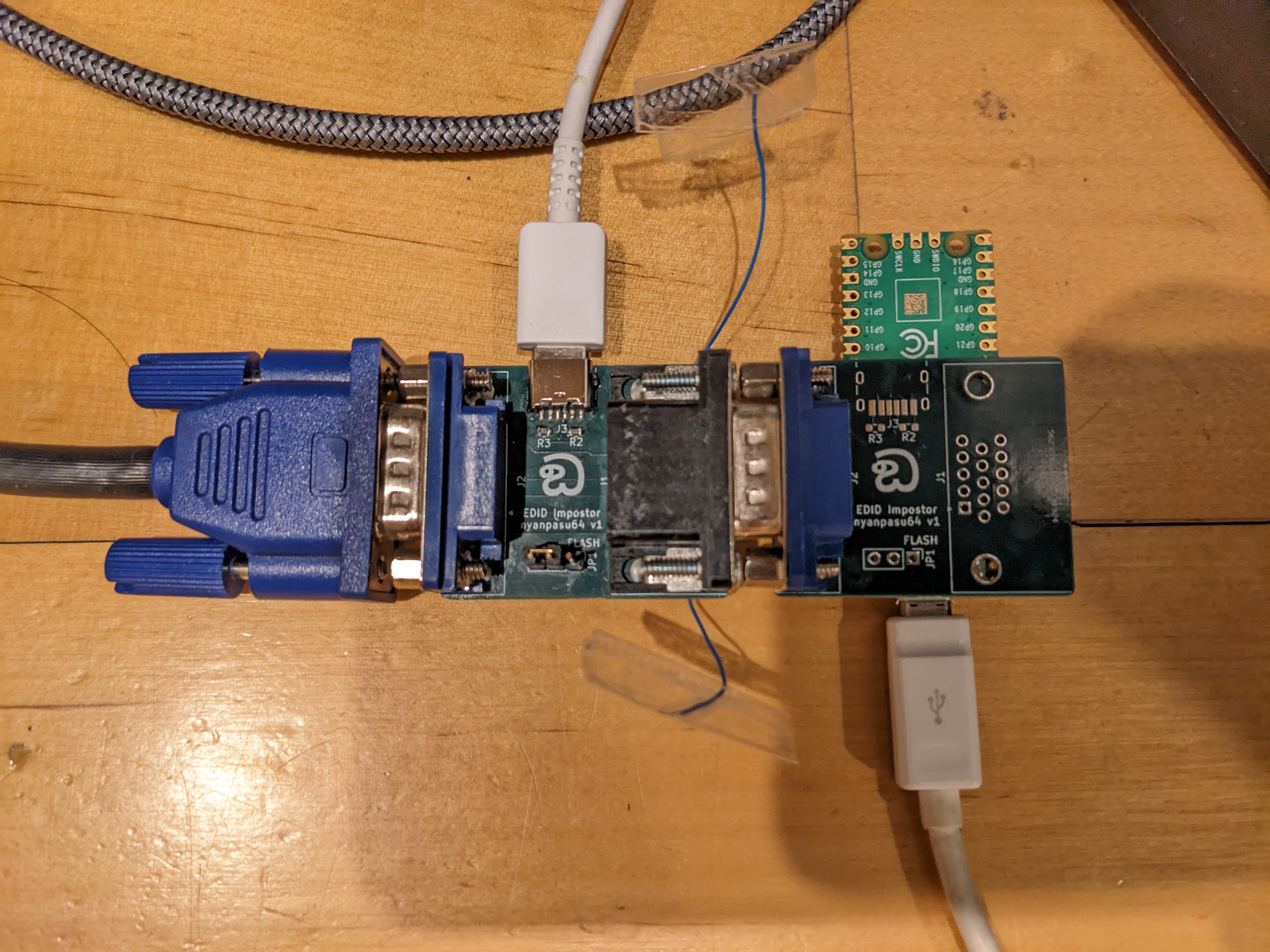
If you want a hardware solution, you can order my PCB at https://codeberg.org/nyanpasu64/vga-edid-powered, but I can't exactly recommend it.
- The male VGA plug has hex nuts which collide with hex nuts on the port, and after removing them the front falls off the port. You have to buy 4-40 screws and use them to either hold the front on, or mount the dongle to a device (depending on which way you install the screws).
- Additionally VGA dongles can't be reprogrammed on a PC through a RTD2166 DP-to-VGA, only through a HDMI or VGA port or an external USB-to-I2C adapter (like rp2040-i2c-interface).
- I recommend using my write-edid program (faster than shell scripts) on Linux to write 128 or 256 bytes to the I2C EEPROM (tested with rp2040-i2c-interface), though others have had success with EDWriter on Windows (only supports video ports).
The advantage to a hardware EDID emulator is that it generally keeps identifying itself even when the monitor is turned off (unlike some VGA monitors which power off their I2C EEPROMs when the power button is toggled off). Also it shares the same EDID resolutions across all your OSes and computers (rather than having to reapply them on every OS when you make a change), though reprogramming the dongle is more work than installing a modeline using xrandr or CRU.
NTI sells a pre-assembled VGA EDID Emulator for $22 plus expensive shipping. This device has functioning screws (though not thumbscrews), and can be reprogrammed, but only with an expensive device which can only clone monitors, and I don't know how to reprogram it from a PC's I2C interface (as I haven't bought the dongle or programmer). I have not tested the $20 Amazon VGA plugs/dongles either.
Interlacing computer monitors
One interesting aspect of CRTs is that you don't have to draw scanlines at the same locations every frame. Instead, broadcast television was built around drawing alternating frames of video in the gaps between the previous frame's illuminated lines, in a process known as interlacing. In the television industry, these "frames" are known as fields, and a "frame" refers to two adjacent fields (so SDTV can be called 30 frames per second, even though the screen is illuminated 60 times per second).
Interlacing (eg. 480i) can produce a more detailed image than half-height progressive scan (eg. 240p), by enabling smoother vertical color transitions, and allowing nonmoving objects to be drawn at twice the vertical detail (at the cost of flicker at half the field rate in high-frequency areas). Compared to repainting the entire screen at the half-field rate, interlacing reduces flicker by doubling how often the image flashes in normal circumstances. Compared to doubling the horizontal scan rate, interlacing requires a lower horizontal sync rate, and half the video bandwidth for equivalent horizontal sharpness.
The downside to interlacing is that if objects scroll vertically at some speeds, they lose increased vertical detail since they move by half a scanline when the field moves by half a scanline. Similarly if your eyes are tracking vertical motion, the entire image will appear half-res with visible scanlines and gaps. And moving/flashing objects will appear combed on every field, if your eyes are not moving in sync with them.
Interestingly, interlacing was not only used in televisions, but also early computer monitors to get high-resolution images from video cards and displays with limited horizontal frequency and signal bandwidth. For example, the IBM 8514 graphics card and monitor (and its successor XGA) could output a 1024x768 signal at 87 Hz field rate, with interlacing (so it only drew a full image at 43.5 Hz)13. I found a description of an 87 Hz mode at http://tinyvga.com/vga-timing/1024x768@43Hz, which matches up with the 44.90 MHz modelines at https://www.mythtv.org/wiki/Modeline_Database, and may match the 8514's timings as well.
- Earlier I was experimenting with interlacing my monitor at 1280x960i120. I found the combing rather annoying on moving cursors and scrolling text, and reverted to 1280x960p75. Perhaps I'd have better luck with higher vertical resolution (so each field's scanlines are denser) and optionally lower field rate.
Another description of monitor interlacing can be found at https://www.linuxdoc.org/HOWTO/XFree86-Video-Timings-HOWTO/inter.html.
If alternating lines are bright and dark, interlace will jump at you.
...use at least 100dpi fonts, or other fonts where horizontal beams are at least two lines thick (for high resolutions, nothing else will make sense anyhow).
Apparently text with thin horizontal lines will flicker when interlaced at a low frame rate. This could prove annoying. So far I've only tried interlacing at a field rate of 120 Hz, and didn't notice 60 hz flicker of fine text.
CRT interlacing on modern GPUs
More recently, CRT enthusiasts have experimented with interlaced timings to extract better resolution and refresh rates from PC monitors. Unfortunately for them, many modern graphics drivers (or worse yet, hardware) are dropping support for interlacing. As a result, people are using old graphics cards and drivers as display outputs, sometimes paired with a modern GPU used to render the actual visuals. One popular pairing is a modern NVIDIA GPU with modern drivers, coupled with an old AMD HD 5450 or similar with a VGA output. Another option is a 900-series NVIDIA GPU with native analog output through DVI-I and a passive VGA adapter, or you could play games on older AMD GPUs instead. Interestingly, on AMD, CRT EmuDriver is not recommended for interlacing (only for low resolutions), as interlacing is supposed to work fine with regular drivers on older cards with analog outputs.
If you want interlacing on a newer GPU, you can feed a digital output through an HDMI-to-VGA dongle. DP-to-VGA dongles are another option, though on Windows only Intel iGPUs can output interlaced resolutions over DP, not AMD or NVIDIA. I've even heard suggestions of rendering games on a NVIDIA card but outputting frames through an Intel iGPU's ports, because they support interlacing over DP and NVIDIA doesn't14, though some people say it adds 1 frame of latency.
- I cannot test interlacing on Windows, since I only have an AMD card and a DP-to-VGA dongle, and trying interlacing gives me no signal.
- On Linux, if you want interlacing from an AMD graphics card through either HDMI or DP, you need to use
amdgpu.dc=0(breaks HDMI audio, cursor doesn't change color with night color) or (on some newer cards) install a kernel driver patch developed by GroovyArcade (bug report). Without either of these changes, you'll get a half-vertical-resolution progressive signal with image width downscaled to half the screen size. - I've heard that on Linux, the proprietary driver doesn't support interlacing on some newer GPU generations, while it still works on nouveau.
I've tested interlacing on a Plugable DP-to-VGA adapter (Realtek RTD2166 chip) with a Gateway VX720 CRT (like Diamond Pro 710). I've noticed that the fields aren't exactly spaced half a scanline apart, but every second gap between scanlines was wider and more visible. This is slightly annoying, but less noticeable than combing during motion.
The XFree86 Video Timings HOWTO says:
You might want to play with sync pulse widths and positions to get the most stable line positions.
I have not tested this. It would also require creating custom modelines, rather than using unmodified GTF or CVT interlaced ones.
- Additionally some modern software can't handle interlaced frame presentation properly. Earlier when I tried playing Stray (a DX11 game) with X11 Wine on an interlaced SDTV, vsync increased input latency drastically, by buffering frames for longer than intended.
Another barrier to interlacing is that many modeline calculators fail to produce proper interlaced modes:
- https://tomverbeure.github.io/video_timings_calculator outputs halved modelines with decimal vtotal values (though the modelines are otherwise accurate, and are X11-compatible after you double all the vertical timings). Additionally it interprets "Refresh Rate (Hz)" as a "frame" (two fields) rate, so the resulting interlaced modes have double the vsync frequency as the number you enter.
- The
cvtprogram also interprets the fps value as a frame (two fields) rate. Worse yet, it outputs halved front porch and sync durations as well as an even vtotal value (CRT interlaced modes usually have an odd vtotal), making the results incorrect.
I think that Windows programs tend to do better; for example, people have had success using Nvidia's custom resolution editor (though I'm not using a NVIDIA GPU and can't verify), as well as CRU's resolution editor.
[NVIDIA] reports interlacing in a brain-hurtful manner lol
Basically NVCP will do something like, for example: 1080i = 66 kHz, and I think can sometimes do something unintuitive with the vertical refresh being halved or doubled what you actually perceive.
But your CRT monitor will staunchly report 1080i as 33 kHz, of course.
CRU takes an interesting approach to building interlaced resolutions.
In CRU, you enter vertical parameters in terms of per-field (half-resolution) line counts, and the program automatically displays the per-frame timings to the right. When set to Manual timings mode, checking the Interlaced box automatically divides the per-field Active textbox by 2 (to keep the per-frame vactive identical and convert it to a per-field vactive), but instead leaves the per-field porch and sync sizes unchanged (reinterpreting the the per-frame timings as per-field ones), then recomputes the per-field Total textbox based on the new active line count.
Building an interlaced modeline
Working with interlaced X11 modelines is tricky, because the numbers actually represent a "virtual" progressive frame produced by weaving two fields together. In interlaced modes, vdisplay, vsync_start, vsync_end, and vtotal are actually computed by adding the time spent in active, front porch, sync, and back porch in two fields of a single frame. (Note that vsync_start and end are off by half a scanline per frame or two fields, see below).
Earlier I was researching the CVT specification and Linux program, to find how to generate a CVT interlaced mode(line). I found bugs in how the Linux library/program generated interlaced modes, and reported a bug in their tracker with my multi-day investigations. Here I'll summarize my final conclusions after piecing the puzzle together.
According to the CVT specification's spreadsheet (on tab CVTv1.2a), the front porch and sync pulse duration are added to each field; this also matches Windows CRU's CVT interlaced mode generator. You're meant to calculate a half-height progressive mode at the same field rate, then generate an interlaced two-field modeline by doubling all vertical timings and adding 1 to vtotal. The modeline's vsync start needs to be 2 front porches* past the vblank start, and the vsync end needs to be 2 vsync durations past the vsync start, so that each field has its own full vertical front porch, sync pulse, and back porch.
- Note that CVT uses the vsync duration to encode signal aspect ratio to a display that understands it. So 640x480i (and its half-height 240p field calculations) has 4 lines of vsync per field to encode 4:3, while regular 640x240p has a 10-line-long vsync representing a non-standard aspect ratio.
(*) Unfortunately interlacing throws a wrench in the calculations. The vtotal value is 1 line more than twice a progressive vtotal, and when an interlaced signal is being transmitted, the total front and back porches are each 0.5 lines longer than twice a progressive porch, leaving the vsync pulse halfway between scanlines. How do we represent this as a modeline?
To look for answers, we'll model the output signal, and see how we could rearrange it to a virtual half-rate progressive modeline.
Assume an interlaced mode with an odd number of lines (=N) per frame (2 fields), and an even number of active lines (you reaaaally shouldn't be using odd resolutions, let alone interlaced).
- In an interlaced mode, hsync and vsync pulses are perfectly periodic. Hsyncs happen every line, but vsyncs occur with a period of x.5 lines (because they occur every N/2 lines, and N is odd).
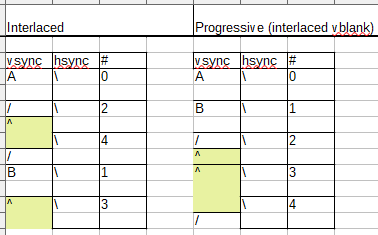
To model interlaced modes, I drew diagrams for two test "mini modelines". Both had odd vtotal (scanline count) per frame (2 fields), and 1 active line per field; the interlaced vblank was placed after either the early field (with longer trailing porches) or late field. (It doesn't matter, both cases have the same issue.)
- In interlaced PC/X11 modes, all active lines begin on hsync boundaries, and both fields start their active period on an integer line (about half a frame apart). Since each full frame has an odd number of lines (unable to be split evenly in two), if we define the length of a field as extending from its first active line to the next field's first active line, then one field is actually 1 line longer than the other field.
- A long field starts (its active period) half a line earlier (relative to vsync) than a short field, enters vblank half a line earlier (relative to vsync), has the same vsync start and stop times (relative to vsync), and ends (with the next field's active period) half a line later (relative to vsync).
- Again, every field's start, blanking, and end timings are always aligned with hsync, while vsync is half a line out of phase with hsync on every other field.
- In a CVT mode with a 2n+0.5 line long (total front porch), a late/short field always comes after an interlaced vsync, not an aligned one.
How do we convert between an interlaced signal and a sequential modeline (representing the timings of two sequential fields)? Return to the diagram of the video signal.
- Assume vtotal is odd. This is always the case for interlaced modes properly generated according to cvt's PDF and spreadsheet.
- First number all scanlines from 0, in increments of 2 modulo vtotal.
- You can rearrange all scanlines so they occur in sorted increasing order, creating an "equivalent progressive" modeline. You will end up with a vsync starting in the middle of a horizontal scanline, which modelines cannot and should not represent.
These mid-line "interlaced vsync" pulses can be encoded as integers in two ways. You can either round them down to the previous scanline (which in a CVT modeline with a 2n+0.5 line long front porch, produces an even front porch length), or round them up to the next scanline (which in a CVT modeline, produces an odd front porch length).
-
I initially thought rounding them to the next scanline made more sense, because the vsync pulse started either halfway through line 2, or on the beginning of line 3. This matches Universal Modeline Calculator as well.
- Unfortunately, when testing on my amdgpu card with Linux and
amdgpu.dc=0, odd front porch lengths resulted in a black screen rather than an image. Interestingly this bug only happened with CVT interlaced modes, not GTF modes (which I generated using https://arachnoid.com/modelines/index.html before adding 1 to the even vtotal). - Worse yet, there's no way that actual drivers could've treated vsync timings as rounded up. https://www.linuxdoc.org/HOWTO/XFree86-Video-Timings-HOWTO/inter.html describes an interlaced modeline with vertical timings
768 768 776 807 Interlace. If drivers interpreted this as beginning a vsync pulse on line 768 or midway through line 767, then the final "visible" line 767's second half would be missing due to screen blanking, or stretched vertically because the vsync pulse pulls the electron beam up before the scanline even finishes drawing.
- Unfortunately, when testing on my amdgpu card with Linux and
-
This means that drivers must be interpreting vsync timings in interlaced modelines as "start the vsync pulse midway through this scanline, or upon the next scanline".
- This is consistent with https://tomverbeure.github.io/video_timings_calculator's modelines, if you multiply all its vertical timings by 2.
I've confirmed that Linux drivers add half a line to vsync timings, by rebooting to amdgpu.dc=0 and probing my DP-to-VGA adapter with my sound card.
- In mode
cvt 640 480 60 interlacewith vertical timings480 486 494 507 ... Interlace, each early field was followed by 3.5 lines of blanking before vsync, and each late field was followed by 3 lines of blanking before vsync (slightly less because my dongle emits vsync pulses slightly before hsync). - When I change the mode to have vertical timings
480 482 494 507 ... Interlace, each early field was followed by 1.5 lines of blanking, and each late field was followed by 1 line of blanking. - Unfortunately when I set the vsync start time to 481 or 480, my drivers and dongle put out no signal (they require that vsync_start >= vdisplay + 2). Similarly, the modeline from https://www.linuxdoc.org/HOWTO/XFree86-Video-Timings-HOWTO/inter.html didn't produce a signal until I changed vsync_start to 770 (768 + 2).
Sidenote: Interlacing in the HD era
In the world of television and video, interlacing has found its way into the modern age.
In the early days of HDTV, before LCD killed off plasma and CRT, some manufacturers released native 1080i HD CRTs. These generally had a fixed horizontal scan rate of 33.75 KHz (1125 lines every 1/30 of a second, split across two fields), displaying fast-moving objects at 540 lines per field. Some HD CRTs supported native 480p scanning at 31.5 KHz as well, for displaying 480i/p content without scaling. (I hear that Panasonic Taus with 31khz support were lag-free in video games, while some other TVs would introduce a frame or two of latency.) If a HD CRT supported 720p content, it would be scaled to 540 lines tall per field before being displayed.
Interestingly, HDMI comes with CEA interlaced modes, a single one of which is interlaced with the forbidden even vtotal (VIC 39 = 1920x1080i with 1250 total). Also https://www.mythtv.org/wiki/Modeline_Database includes multiple interlaced 1080i modes with a vtotal of 1124 rather than 1125. I'm not sure what actual HD CRTs used.
Surprisingly, interlacing has survived the transition from analog SDTV to digital HDTV. ATSC broadcast TV is built around either 720p or 1080i video transmitted using the MPEG-2 codec. 1080i offers more total detail for near-static images, but requires deinterlacing algorithms if shown on LCD TVs, and offers inferior vertical resolution for moving objects, so sports broadcasts generally run on 720p instead. ATSC is also a victim of the corruption pervasive among commercial standards using patented technology (to quote Wikipedia):
With MUSICAM originally faltering during GA testing, the GA issued a statement finding the MPEG-2 audio system to be "essentially equivalent" to Dolby, but only after the Dolby selection had been made.[1] Later, a story emerged that MIT had entered into an agreement with Dolby whereupon the university would be awarded a large sum if the MUSICAM system was rejected.[2] Following a five-year lawsuit for breach of contract, MIT and its GA representative received a total of $30 million from Dolby, after the litigants reached a last-minute out-of-court settlement.[2] Dolby also offered an incentive for Zenith to switch their vote (which they did), however it is unknown whether they accepted the offer.[2]
Outside of North America, most television is based on DVB-T (also MPEG-2 at 720p or 1080i) or DVB-T2 (H.264 up to 1080p50). I hear many countries still primarily broadcast on DVB-T, but Thailand uses DVB-T2 but still broadcasts in 1080i50, presumably to save bandwidth compared to 1080p50.
Another place I've found interlacing is when I pulled the SD card out of my Sony Alpha a6000 camera, and found a large video file with an odd .MTS extension. Opening it in mpv, I was surprised to see combing in moving objects, because mpv had used comb reconstruction rather than a proper deinterlacing algorithm. After pressing the d key, the video became more watchable, though I still noticed artifacts in fine detail (whether from deinterlacing or video compression).
- I found that the .mts file was recorded in AVCHD format, which is a container for H.264 video in 1080i resolution with AC-3 audio (Dolby Digital), output by many camcorders.
- There's an entire community of media and anime fans who research complex and CPU/GPU-intensive video upscaling, interpolation, and deinterlacing algorithms to watch their videos in the highest quality (subjectively). I found a Reddit post about configuring mpv to pick between multiple types of deinterlacing, including CPU and GPU/CUDA algorithms. I'm not sure which deinterlacer mpv uses by default.
Newer compression algorithms like H.265 and VP8/9 do not support interlacing at the compression level. I think interlacing creates more problems than it solves, for digital video transmitted to LCD displays (ATSC and DVB-T may have reasonable given limited bandwidth and the codecs of the time, but interlaced H.264 is questionable), and hope that it remains a thing of the past.
Footnotes
We plugged in one such, and when the switch came to 15khz? It exploded. Like, the magic grey smoke escaped, along with flames and melting plastic.
I did let the smoke out of one monitor with a bad X modeline.
mikekchar commented about a modeline db.
lizknope commented on Hacker News:
I remember creating a new modeline and adding it to the list. Then using ctrl+alt and +/- to cycle through the modes. I would get to the new mode and the monitor would start buzzing and clicking and the image would flicker. I would quickly toggle to the next mode that was "safe" then go back and edit the modeline and try again.
http://martin.hinner.info/vga/640x480_60.html (I'm not sure why it says 2 lines vertical sync, but the oscilloscope photo shows 3 lines of vsync pulse)
If you are trying to drive a display past its self-reported frequency/pixel clock limits, some users report that you must first override the EDID through the Linux command line. Others report you can pick custom resolutions on a CRT without installing a spoofed EDID binary.